Subfaces, canopy, and comfort point
![]()
![]()
![]()
A wall may contain openings, which are divided into windows, rooms, panels, and construction sections. Additionally a canopy/screen may be present on the wall. These elements can be placed into a wall using the functions in the sub-screen Subface.
Add subface
![]()
With this option you can add a window, door, panel, or construction section to an existing surface. This surface may be a roof, a floor, or a wall.
Edit surface
You can adjust a subface by right-clicking on the subface.
You can then adjust the dimensions and the placement within the main surface.
Step-by-step guide to adding a subface
Click the construction face in which you would like to create a subface,
Select the type of subface: window, door, panel, or construction section
Within this sub-screen Subface dimensions, indicate whether the dimensions of the subface are determined as a percentage of the main face, or by specifying these dimensions Depending on this choice, you may then specify a percentage (%) or two dimensions (WxH in mm). In the latter case, first the width and then the height are specified.
When choosing the placement to be automatic, the subface is centred (if Percentage was used), or placed in the bottom left of the main face (if dimensions was used). The placement of the subface may also be done using custom values, in which the subface is located X mm from the left edge of the face and Y mm from the bottom edge.
Click “Ok”, after which the subface is located in the selected main face.
If you click the “X” in the top right of the sub-screen, the action is cancelled and the subface is not created.
- Optionally, you can move the subface to the right location using the Move.
Add canopy
![]()
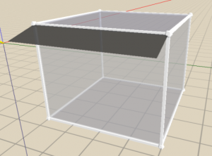
This function allows to you create a canopy at every drawn line.
Click Add canopy in the sub-screen Subface of the menu bar, or press the B.
Click on the face and the line at which you want to create the shed. The following sub-screen will appear:
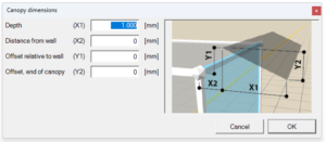
The canopy will be dimensioned based on the line selected in step 2:
The illustration next to the input fields indicates how the canopy dimensions are defined with respect to the selected line. Specify the following dimensions:
- Depth (X1) is the depth of the canopy perpendicular to the selected face.
- Distance from wall (X2) is the offset of the canopy perpendicular to the selected face.
- Offset relative to wall (Y1) is the offset of the canopy parallel to the selected face.
- Offset end of canopy (Y2) is the slope of the canopy measured parallel to the selected face.
If you click on “Ok” button, the canopy is created. If you click on the “X” button, the action is cancelled and the canopy is not created.
Read more about shading here.
Place comfort point in room
- Gebouwsimulatie
![]()
The comfort point will automatically be placed in the centre of the room by the software. A complex shaped room can give the error notification that the software is unable to place a comfort point. With this tool you can place the point yourself, however, the height of the point is always 80 cm from the floor.
Step-by-step guide to placing the comfort point
Click where you would like to place your comfortpoint.
Now click on the location in the room where you want the comfort point to be.
From step 3, you can also use the following steps:
To place a comfort point, you can specify the value for the X-axis or the Y-axis by entering the distance [mm] as follows: 450;350.