Heat loss
Under the Heat Loss menu, you will find the results of the Heat Loss module. The Heat Loss module contains two types of results: tables and reports.
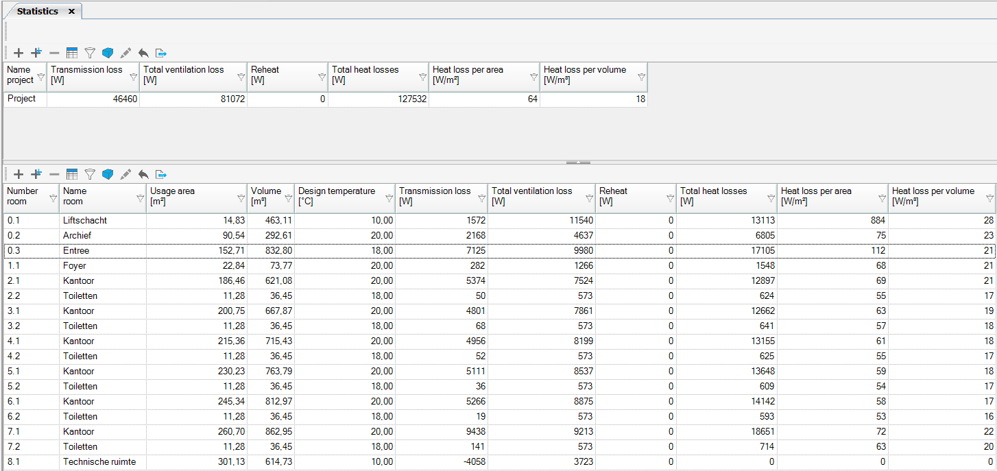
Statistics
In the statistics, you will find an overall summary and, per room, the various components for Heat Loss. The generic functions of the tables can be found on the Tables webpage. This also allows the results to be displayed in 3D.
Statistics 2017
Statistics on building (complex) level 2024

| Name building | Name building |
| Generation configuration | Collective or individual |
| ΦT,ie [W] | Heat loss due to transmission to the outside |
| ΦT,iae [W] | Heat loss due to transmission to adjacent unheated spaces |
| ΦT,ig [W] | Heat loss due to transmission to the ground |
| Φi [W] | Heat loss due to infiltration |
| Φgain [W] | Heat gain |
| Φbasis [W] | Basic heat loss |
| ΦT,iaBE [W] | Heat loss due to transmission to an adjacent building |
| Φvent [W] | Heat loss due to ventilation |
| Φhu [W] | Reheat factor |
| Φextra [W] | Heat losses that do not always (simultaneously) occur |
| Φadd [W] | System losses |
| Φgain, v* [W] | Heat gain ventilation |
| ΦHL, verd. [W] | Power generator/flow through divider |
| ΦHL,v per opp [W/m²] | Power generator/flow through divider per surface area |
| ΦHL,v per vol [W/m³] | Power generator/flow through divider per volume |
Statistics on room level 2024

| Name room | Name room |
| ISSO | Calculated according to ISSO |
| Heat. | Room is heated |
| Temp [°C] | Design indoor temperature |
| fk | Correction factor to adjacent unheated spaces (ISSO 51 and 57 table 2.3, ISSO 53 table; 2.5) |
| ΦT,ie [W] | Heat loss due to transmission to the outside |
| ΦT,iae [W] | Heat loss due to transmission to adjacent unheated spaces |
| ΦT,ia [W] | Heat loss due to transmission to heated spaces in the building |
| ΦT,ig [W] | Heat loss due to transmission to the ground |
| Φi [W] | Heat loss due to infiltration |
| Φgain [W] | Heat gain |
| Φbasis [W] | Basic heat loss |
| ΦT,iaBE [W] | Heat loss due to transmission to adjacent building |
| Φvent [W] | Heat loss due to ventilation |
| Φhu [W] | Reheat factor |
| Φextra [W] | Heat losses, not always occurring (simultaneously) |
| ΦHL,i [W] | Design power room |
| ΦHL,i per opp. [W/m²] | Design power room per area |
| ΦHL,i per vol. [W/m³] | Design power per volume |
| Φadd [W] | System losses |
Transmission per room
| Description | Name of the construction |
| Type | Floor, Wall, Ceiling, Roof, Sl. Roof, Door, Window, Panel |
| Oriën. [°] | Angle towards north |
| Cz [-] | Cz value, in case of neighbours (ISSO 51, table 2.16) |
| Area [m²] | Area of the construction |
| Uk/Ueq value [W/m²K] | Calculated U value, floors on ground: Ueq |
| dUtb [W/m²K] | Additional value on the U-value of constructions due to thermal bridges. Type of building. |
| Adj. Temp. [°C] | Adjacent temperature |
| Temp. Grad. [K] | Temperature gradient, depending on chosen heating system (ISSO 51 table 2.12, ISSO 53 table 2.16, ISSO 57 table 2.13) |
| fk [-] | Factor to adjacent unheated rooms (ISSO 51 en 57 table 2.3, ISSO 53 table; 2.5). In case of floorheating factor equals 0: no transmission through the floorconstruction. |
| Transmission [W] | Transmission through the construction. In case of floorheating: no transmission through the floor. |
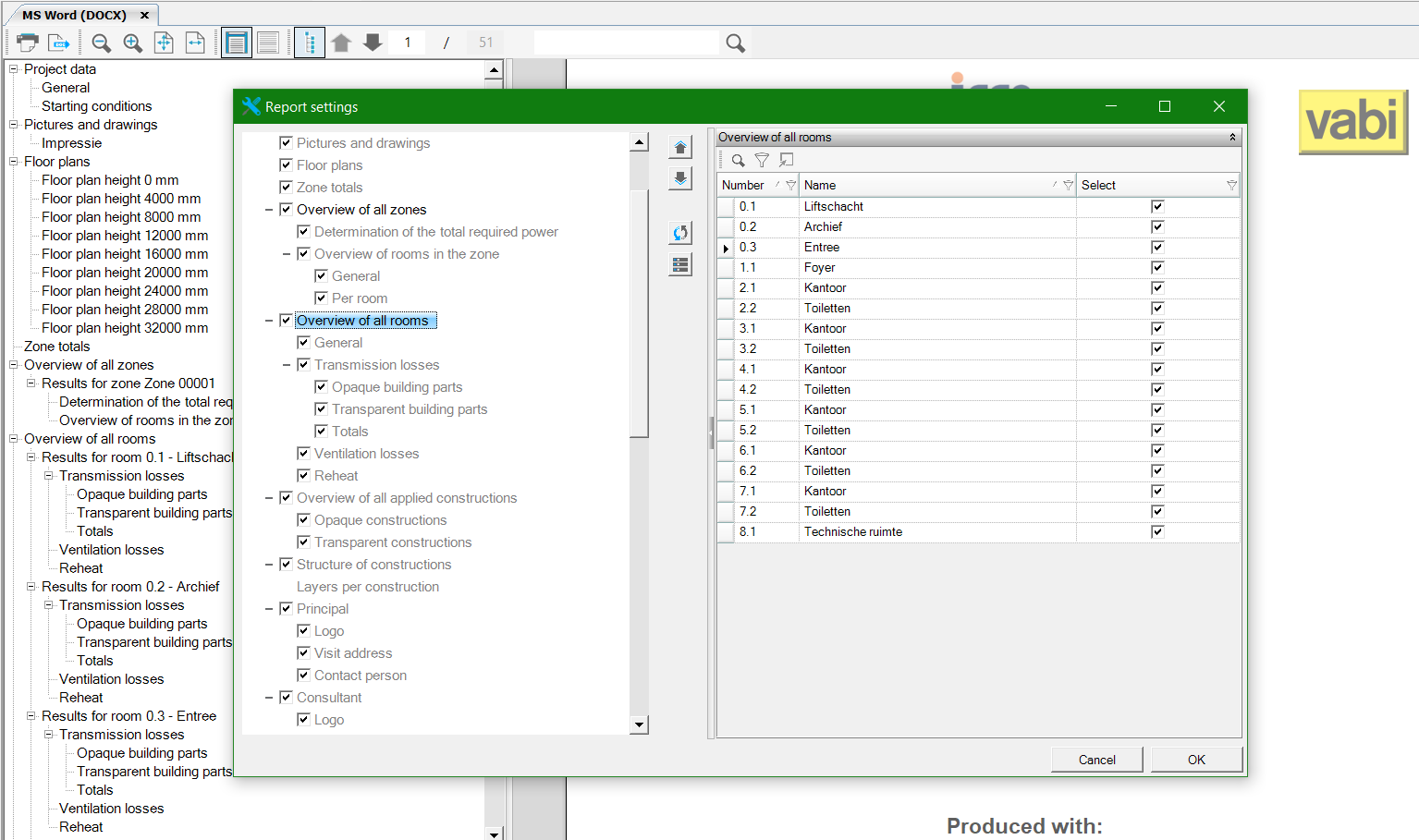
Flexible Word Report (docx)
The Word report for Heat Loss can be arranged flexibly. Adjust the layout in MS Word (DOCX) settings before recalculating Heat Loss at Calculation Status. These settings allow:
- Flexible chapter order
- Toggle chapters on/off
- Toggle rooms and zones on/off
- Automatically generated floor plans
- Unlimited images via project settings
- Improved Word export with navigation pane and table of contents
In the Word report, you find all results and assumptions. Navigate using the left menu. The top toolbar offers various view options.
Toolbar functionality:
- Print/export to Word
- Jumping to a page shows its top
- Scroll updates page number
- Search updates live, continues with F3 or magnifier
Images in the report
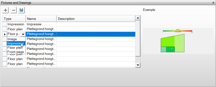
New in the Heat Loss report is the ability to add an unlimited number of images. You can add images to the report by uploading them in Project Data. You can also save a 3D image in the geometry section, which can be found under Photos and Drawings. Floor plans are automatically included in the report.
An image’s placement in the report depends on its type (Cover Page/Floor Plan/Image/Impression).
Cover Page
- Warmteverlies
The first image under project data with the type Cover Page is used for the cover page of the report.
Image
All images with the type ‘Image’ are included in the report.
Floor plan
- Warmteverlies
In the heat loss report, floor plans are added automatically. You do not need to generate these with the floor plan button. This button is still available for other reports as long as the report has not been updated there.
All images generated with the Save Floor Plans button are automatically given the type Floor Plan. These are not included in the heat loss report because the floor plans are generated automatically during the calculation. If you still want to add the floor plans to the report, you need to change the type to Image.
Floor plans generated during the flow visualization Ventilation Flows WV are included in the report.
Impression
- Warmteverlies
Impressions are not included in the heat loss report. If you want them to be included, change the type to Image.
Text (TXT)
The Text (TXT) report contains the same sections as the Word report. This report can be printed and exported as a PDF.