2D CAD Import wizard
2D CAD drawing programs are often used to quickly load geometry into Vabi Elements. This is especially useful and efficient for larger buildings. With the 2D CAD import feature, you can step-by-step import and convert the 2D CAD drawing into 3D geometry in Vabi Elements. When setting up a CAD drawing, there are several points to consider to ensure error-free geometry in Vabi Elements.
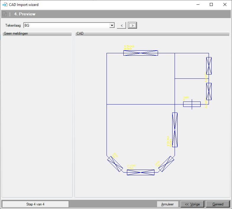
Take a look at the example of how the 2D CAD import of a residential building looks.
10 points of attention for the 2D CAD drafter
1. Create a separate drawing layer for each building level
Create a separate drawing layer for each building level in the CAD drawing program you are using. Ensure that these building layers are neatly stacked on top of each other. This way, the building levels will also stack correctly in Elements to form a multi-story building.
2.Draw walls using single lines.
Each line is considered the centerline of a wall. In a drawing where multiple lines define a wall, this should be avoided as it will be interpreted as separate spaces. Construction thicknesses, cavities, and dropped ceilings are specified in Elements under Tools-Construction.
3. Ensure that lines connect properly to each other.
Make sure all your lines are drawn neatly. When lines do not connect properly, the space cannot be formed. Sometimes you may need to zoom in on your drawing to see if your lines connect correctly.
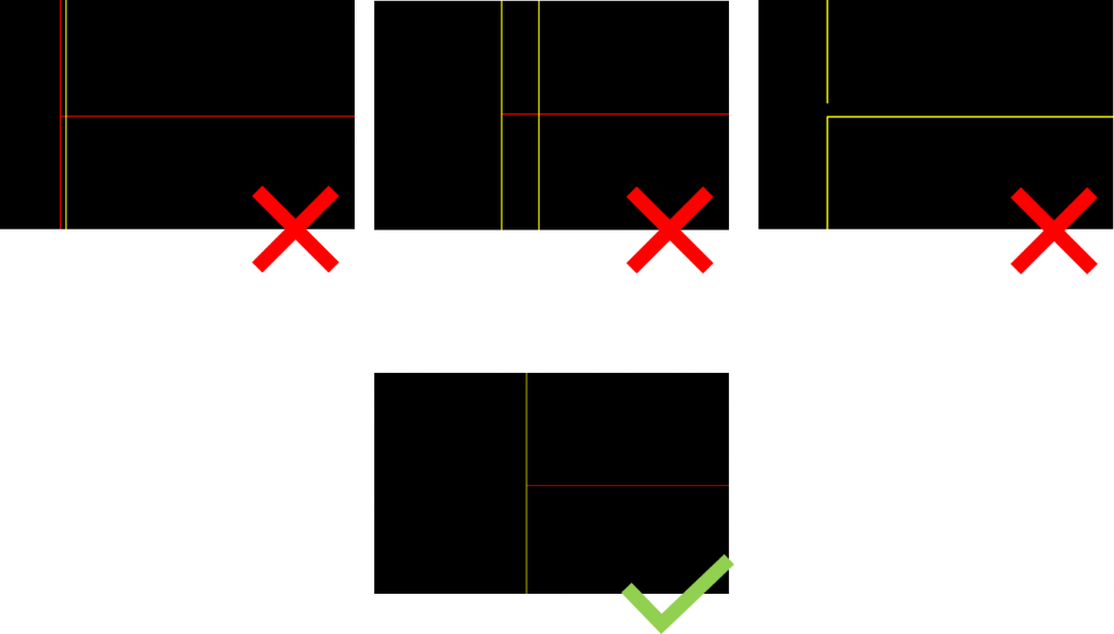
4. Where possible, ensure that lines are perfectly aligned with each other.
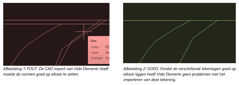
When lines are not drawn neatly aligned, it can lead to various construction and boundary issues. For instance, a construction that should represent an intermediate floor might be interpreted as a roof. Moreover, it can slow down computational time because each area is calculated separately. When lines are drawn closely together but not perfectly aligned, in Vabi Elements’ 3D geometry, the lines may be pulled towards each other. This can affect the rest of the space and cause distortions.
Red dots and surfaces in the geometry often indicate lines that are not precisely aligned on top of each other.
5. Save time by using blocks for windows, doors, and panels.
In Vabi Elements, windows, doors, and panels are created as sub-surfaces of a construction. In your CAD drawing, you can indicate windows, doors, and panels using blocks.
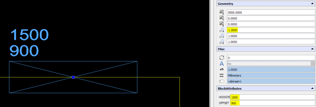
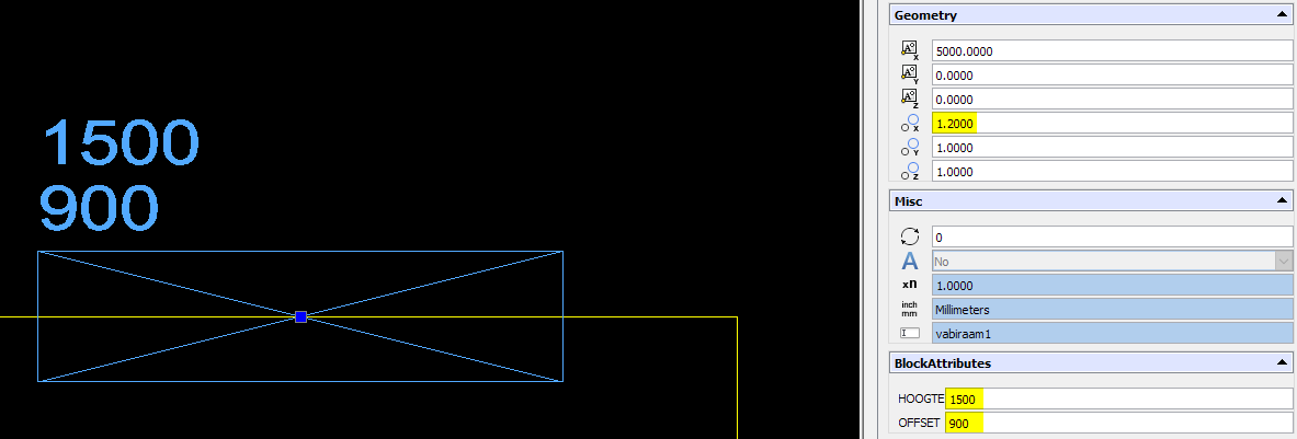
Tip: Copy the blocks from our sample projects and place them with the insertion point on the line of the respective wall. Adjust the width by changing the X-factor and specify the height using the attribute HEIGHT, and the floor offset using OFFSET.
- Note: Do not place windows directly adjacent to each other; ensure there is always some space between them.
- Also, be careful not to overlap two windows on top of each other.
6. Use room names and numbers in the CAD drawing.
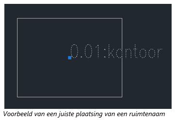
Save a lot of time by indicating room numbers and names directly in the CAD drawing. This makes it easy to later link templates to room names. For example, when specifying the description of a room as “0.01: Office,” the colon (‘:’) is seen as the separator between the room number and the room name. Pay attention to the following points:
- The location of the insertion point/base point of the text must be within the corresponding room. If the text is outside the room, ensure the insertion point is inside the room.
- Room names can be on the same drawing layer as the drawn rooms. Alternatively, room names can be on a separate drawing layer. You can choose the layer containing room names in step 3 of the 2D import wizard.
- Text before the colon is interpreted as the room number and room name.
- Text without a colon is interpreted as the room name, and the room number is left blank.
- Text should be entered as single-line text and not as multi-line text.
7. Pay attention to double-drawn lines or windows.
When two lines are drawn on the same layer overlapping each other in a CAD drawing, issues may arise when importing into Vabi Elements. This also applies when using blocks for windows and doors, ensure they never overlap.
If a room is not imported correctly, check for any instances where components are double-drawn.
8. Make sure to save with the correct file extension.
Save a 2D CAD drawing as .dwg or .dxf so it can be imported into Elements. Note that not every version of .dxf and .dwg can be imported. The latest version supported for import is R2018.
9. Read the errror messages.
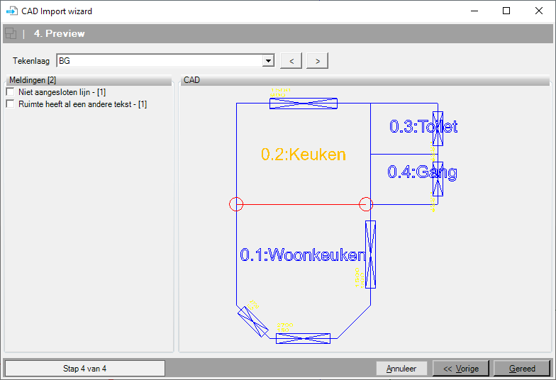
The final screen of the CAD Import wizard displays a preview of the CAD drawing and shows any error messages per layer. It’s always advisable to thoroughly check all building layers here.
10. Check the 3D geometry for errors.
After importing the geometry, it’s advisable to always double-check for errors. There may be issues in the geometry that aren’t indicated by error messages. It’s almost always better to make adjustments in the CAD software rather than trying to resolve red dots and surfaces in Vabi Elements later on.
Always check the following points:
- Set the view to make partition walls non-transparent and ensure all exterior walls are transparent while interior walls are not. Are there transparent partition walls or floors? This could indicate a very complex space where floors are not properly defined. It might help to split large or complex spaces in the CAD drawing.
- Check for red surfaces and dots. If present, identify the cause and resolve it in the 2D CAD drawing.
- If a room is not imported correctly, check if windows or walls are double-drawn in the CAD drawing and remove any duplicates. Windows or doors that are drawn adjacent to each other or overlap can also prevent the room from being imported correctly.
- If a partition wall is not drawn, ensure that this line in the CAD drawing connects properly with other lines.

When lines are not drawn neatly aligned, it can lead to various construction and boundary issues. For instance, a construction that should represent an intermediate floor might be interpreted as a roof. Moreover, it can slow down computational time because each area is calculated separately. When lines are drawn closely together but not perfectly aligned, in Vabi Elements’ 3D geometry, the lines may be pulled towards each other. This can affect the rest of the space and cause distortions.
Red dots and surfaces in the geometry often indicate lines that are not precisely aligned on top of each other.
Tip: Copy the blocks from our sample projects and place them with the insertion point on the line of the respective wall. Adjust the width by changing the X-factor and specify the height using the attribute HEIGHT, and the floor offset using OFFSET.
- Note: Do not place windows directly adjacent to each other; ensure there is always some space between them.
- Also, be careful not to overlap two windows on top of each other.
Save a lot of time by indicating room numbers and names directly in the CAD drawing. This makes it easy to later link templates to room names. For example, when specifying the description of a room as “0.01: Office,” the colon (‘:’) is seen as the separator between the room number and the room name. Pay attention to the following points:
- The location of the insertion point/base point of the text must be within the corresponding room. If the text is outside the room, ensure the insertion point is inside the room.
- Room names can be on the same drawing layer as the drawn rooms. Alternatively, room names can be on a separate drawing layer. You can choose the layer containing room names in step 3 of the 2D import wizard.
- Text before the colon is interpreted as the room number and room name.
- Text without a colon is interpreted as the room name, and the room number is left blank.
- Text should be entered as single-line text and not as multi-line text.
When two lines are drawn on the same layer overlapping each other in a CAD drawing, issues may arise when importing into Vabi Elements. This also applies when using blocks for windows and doors, ensure they never overlap.
If a room is not imported correctly, check for any instances where components are double-drawn.
Save a 2D CAD drawing as .dwg or .dxf so it can be imported into Elements. Note that not every version of .dxf and .dwg can be imported. The latest version supported for import is R2018.
The final screen of the CAD Import wizard displays a preview of the CAD drawing and shows any error messages per layer. It’s always advisable to thoroughly check all building layers here.
After importing the geometry, it’s advisable to always double-check for errors. There may be issues in the geometry that aren’t indicated by error messages. It’s almost always better to make adjustments in the CAD software rather than trying to resolve red dots and surfaces in Vabi Elements later on.
Always check the following points:
- Set the view to make partition walls non-transparent and ensure all exterior walls are transparent while interior walls are not. Are there transparent partition walls or floors? This could indicate a very complex space where floors are not properly defined. It might help to split large or complex spaces in the CAD drawing.
- Check for red surfaces and dots. If present, identify the cause and resolve it in the 2D CAD drawing.
- If a room is not imported correctly, check if windows or walls are double-drawn in the CAD drawing and remove any duplicates. Windows or doors that are drawn adjacent to each other or overlap can also prevent the room from being imported correctly.
- If a partition wall is not drawn, ensure that this line in the CAD drawing connects properly with other lines.
Requirements for CAD drawings
For each floor, a floor plan must be drawn on a separate layer, where each wall consists of a single line. These single-line objects, such as polylines, lines, and similar entities, should be placed in the middle of the wall so that after import, the dimensions of a room with center-to-center measurements are known. To properly read the layout of the building and its data from a CAD file, the drawing must meet the following conditions:
- Double-lined drawings, where walls consist of more than one single line, should be avoided. Drawing lines over each other can cause problems where a line ‘stops’ halfway through a wall.
- Ensure that the floors are correctly layered above each other.
- A floor should not be divided across multiple drawing layers.
- Lines representing walls must seamlessly connect with each other. It should be noted that it’s not always visible whether the walls connect properly.
- Lines that do not serve to define rooms will be removed during CAD import.
- Set the height of the layer (Z-values) to 0.
When line segments in the CAD drawing are placed at high coordinate values, multiple rooms may not be positioned correctly or may overlap. In this situation, it is necessary to move all line segments of all layers (floors) towards the origin.
Ideally, all lines should align precisely. If lines from different drawing layers are not properly aligned, Vabi Elements may struggle to define them as separate floors. This can result in various surfaces with different boundaries (sometimes a floor, other times a ceiling, etc.). Apart from complicating import, the computational core also faces challenges because it must calculate each surface separately. Therefore, it is advised to ensure that drawing layers are properly aligned.
Windows, doors, and panels
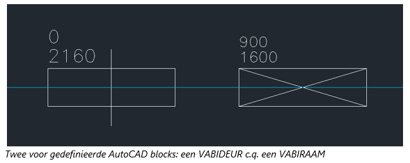
Windows, doors, and panels can be imported via CAD by creating and placing an AutoCAD block in the drawing. The block should indicate the wall in which the window, door, or panel is located and specify its dimensions. Two attributes added to the block allow for passing the height and vertical offset (height below the sill above the floor). The width of the window, door, or panel is adjusted using the x-factor attribute.
Windows, doors, and panels are defined within Elements as partial areas and are placed accordingly within the respective main wall. Here are the key considerations:
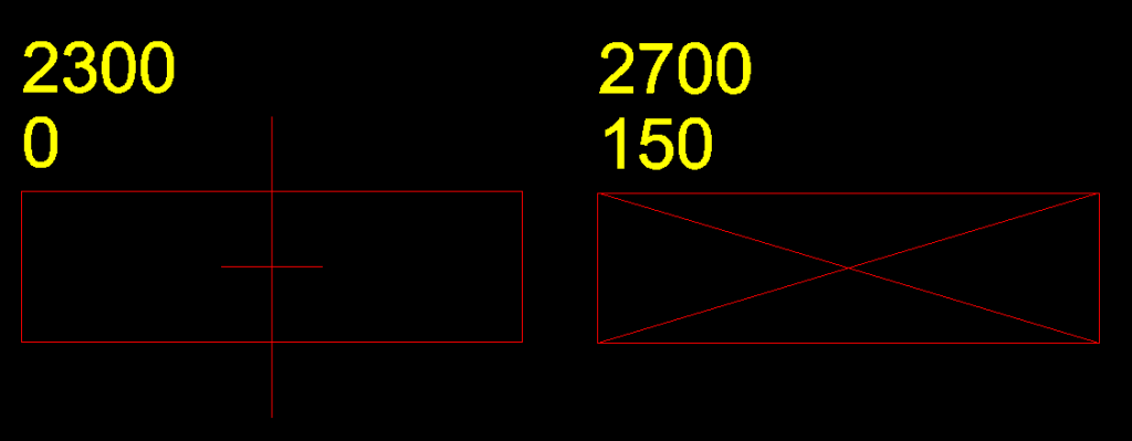
- Windows, doors, and panels are defined by creating a block on layer 0 (zero). As an example, draw a rectangle (consisting of 4 line segments) where the length of the longest line segment is 1000 mm.
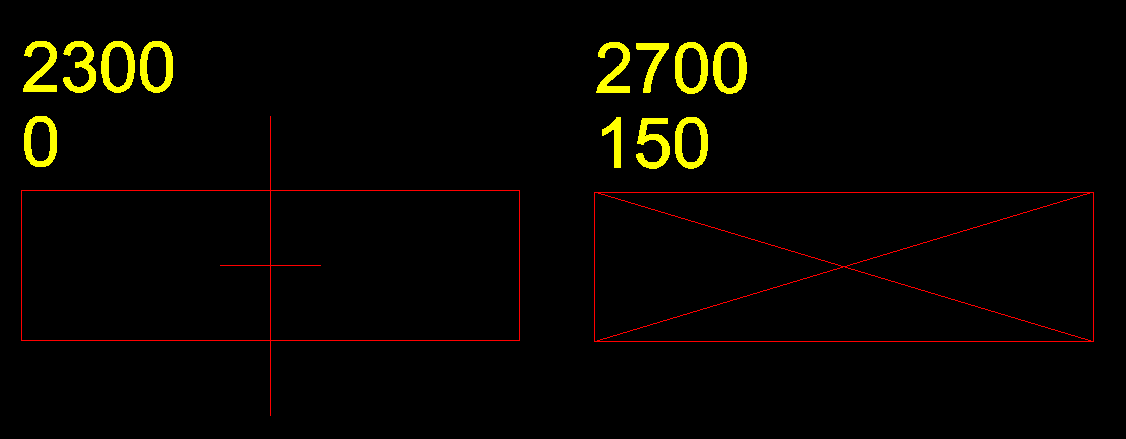
- Next, place 2 attributes preferably above the rectangle. In the first attribute, specify the height (HOOGTE) of the door, window, or panel. In the second attribute, specify the vertical offset (OFFSET, height below the sill above the floor).
- After defining the attributes, define the block. When defining the block, both the rectangle (line segments) and the attributes must be selected as objects.
- The insertion point, or Insertion Point, must be specified in the center of the rectangle.
- The rectangle must have a length of 1000 mm. If the window, door, or panel has a different width, this can be specified during placement using the x-factor. For example, if the window is 0.80 m wide, specify an x-factor of 0.8 (the y-factor remains 1.0).
- The content (figure) of the block is irrelevant.
- The name of a block can be freely chosen but must be identical for all blocks of the same type.
- The name of an attribute can also be freely chosen.
- Subsequently, place the block on the correct drawing layer of the respective wall. The insertion point of the block must lie on the wall.
- The position of a window, door, or panel in the wall (location of the insertion point) is transferred to Elements. It is assumed that this point is in the middle of the window, door, or panel.
These guidelines ensure that windows, doors, and panels are accurately represented within Vabi Elements when imported via CAD, maintaining consistency and functionality in the modeling process.
Room names
The program initially assigns room numbers automatically. However, it is also possible to specify room numbers via the CAD drawing. For instance, if the room description includes text like “0.01:Office,” the colon (‘:’) serves as a separator between the room number and the room name:
- The location of the insertion point (or Base Point) of the text must lie within the corresponding room. If the text extends outside the room boundary, ensure the Insertion Point is still within the room.
- Room names can reside on the same drawing layer as the drawn rooms. Alternatively, room names can be designated on a separate drawing layer.
- Currently, only Single Line Text is fully supported. Multi Line Text can also be imported but may contain unnecessary characters.
- Text before the colon is interpreted as the room number (up to a maximum of 5 characters).
- Text after the colon is interpreted as the room name.
- Text without a colon is considered as the room name, leaving the room number field blank.
These guidelines help ensure that room numbers and names are accurately conveyed from the CAD drawing into Vabi Elements, facilitating efficient data input and management within the software.
Curved wall
The term “curved wall” refers to walls that are drawn as (part of) a circle, ellipse, or have some other form of curvature. For these, the following conditions apply:
- Draw the wall as a polygon, not as an arc. Using the arc function can lead to issues with overlapping spaces.
Room-in-room
For versions older than 3.2 of Vabi Elements, a specific drawing technique is required for room-in-room configurations. This is because it’s not possible to create a hole in a plane, both in terms of geometry and calculation modules. Therefore, “island formation” or “island formation” is not allowed. At least two guidelines must be added to define the planes.
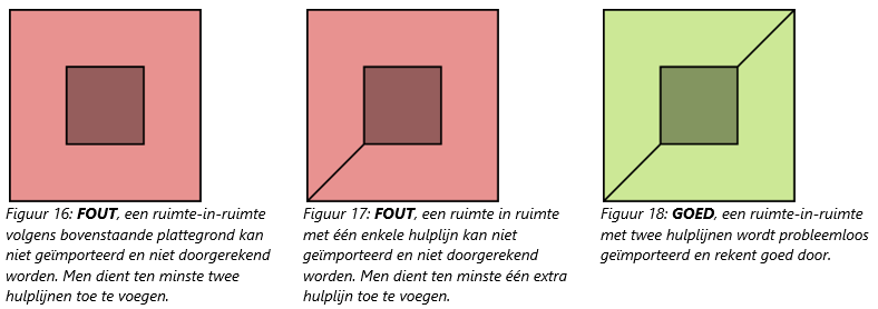
The above situations also apply if the room-in-room configuration spans across different floors (bouwlagen) above each other.
Supported file types
Vabi Elements supports all the versions of AutoCAD listed below. (See also Version History van DWG op Wikipedia.)
- DXF, versions; 12, 13, 14, 2000, 2004, 2007, 2010, 2013, 2018
- DWG, versions; 13, 14, 2000, 2004, 2007, 2010, 2013, 2018
Step-by-step CAD drawing guide
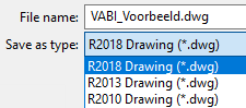
Create file
Open the CAD program (e.g., AutoCAD or DraftSight) and create a new drawing. Give it a clear name and save it as “2018 Drawing (*.dwg)”.
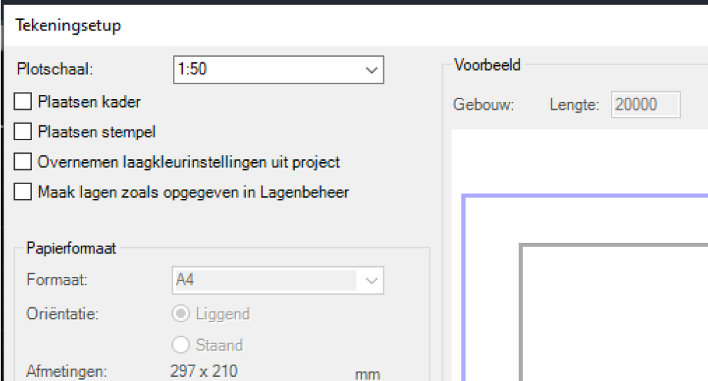
If you are using a base map to draw the spaces, ensure that the scale of your drawing matches the base map. Elements operates in millimeters, so the dimensions in your CAD drawing should also be entered in millimeters.
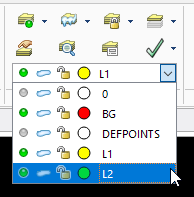
Create layers
Here’s the translation of your text into English:
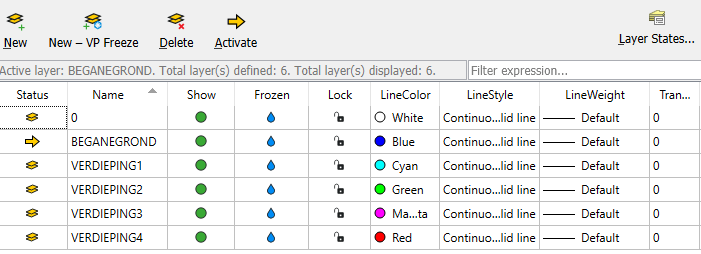
The Elements CAD import creates a building layer in the 3D model for each selected CAD drawing layer. Therefore, it’s useful to create all these layers in advance so you can use them during drawing.
In the CAD drawing, alongside the standard 0 (zero) layer, create as many additional layers as there are building layers in the building. Make sure these layers have easily recognizable names so they can be easily found in Elements. Additionally, start with the ground floor (or any basement) and build the layers upwards. This way, the layers will already be in the correct order for the Elements import, and you won’t need to rearrange them later.
Furthermore, it’s helpful to assign a unique color to each layer so it’s easier to see which layer you are drawing on later.
Drawing building levels
For Elements CAD import, it’s necessary that spaces are drawn with single lines. This means each wall should be represented as a single “Line”. In the case of a curved wall, it should be divided into straight segments using “Line”. Alternatively, you can use “Arc”, but this may cause issues if it spans multiple floors.
In Elements, wall dimensions are center-to-center measurements, so they should be drawn accordingly in the CAD drawing. If you’re using a base map, ensure the Lines run through the center of the walls on the base map.
To ensure proper recognition in Elements, the entire layer should be drawn at height z = 0. Otherwise, it may not be recognized. Additionally, it’s crucial that Lines connect precisely without overlapping.
Use Lines to outline all walls thoroughly so that each space in the building layer is represented in the layer.
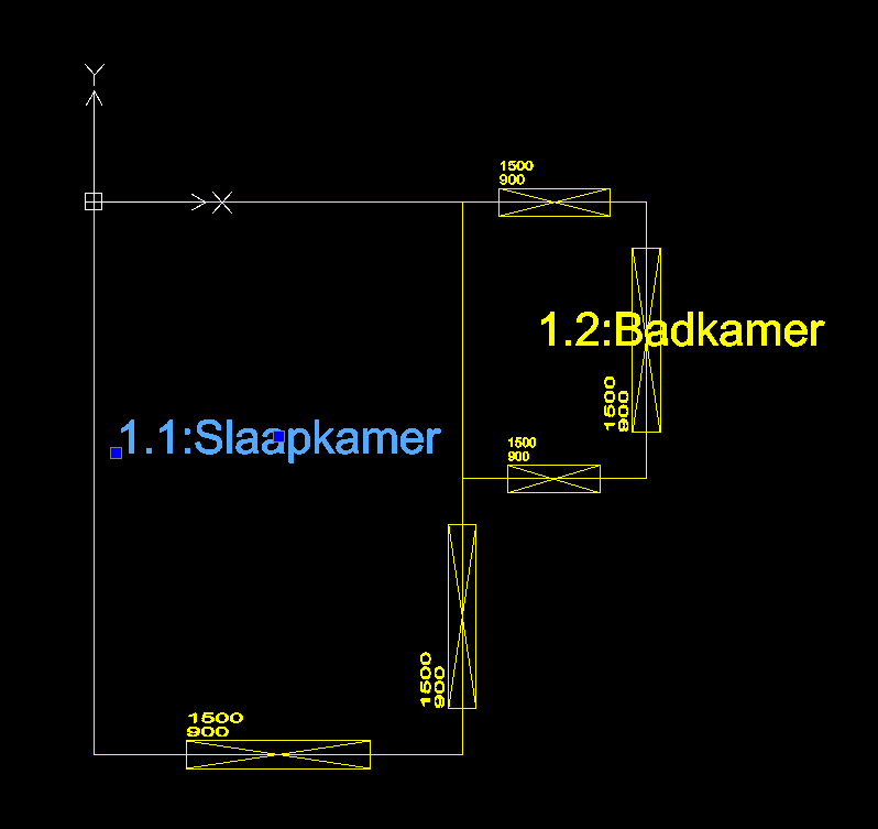
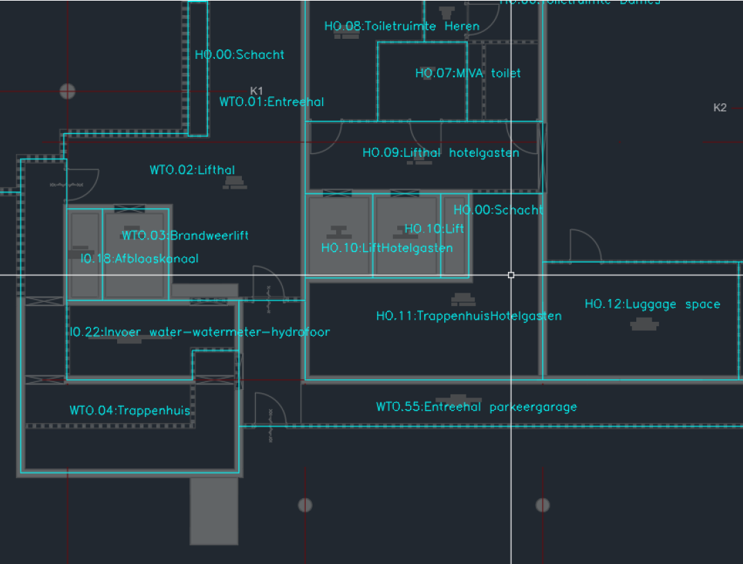
If desired, room numbers and names can be assigned to spaces in advance using “Single line text”. The format should be Room Number:Room Name. When the insertion point (blue dot) of the Single line text is within the space, it will automatically link to that space in Elements.
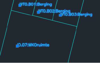
Hierna zouden zowel de ruimtes als de ruimtenamen/-nummers in de tekening moeten staan, zoals bij het voorbeeld hieronder.
Adding windows, doors, and panels
Once the spaces are defined, windows, doors, and panels can be added if desired. Each of these building components can be added using a Block.
Windows, doors, and panels are defined by creating a Block on layer 0 (zero). As an example, you can draw a rectangle (using 4 line segments) where the length of the longest line segment is 1000 mm. Next, place 2 attributes preferably above the rectangle. In the first attribute, specify the height (HEIGHT) of the door, window, or panel. In the second attribute, specify the vertical offset (OFFSET, height from the threshold to the floor). After this, define the Block. When defining the Block, select both the rectangle (line segments) and the attributes as objects.
It’s also possible to use Blocks from the example Project A. This project includes all three types of Blocks, so if you copy them to your current project from %ProgramData%\Vabi\Elements\Examples\NL\ProjectA.dwg, you won’t need to redefine them yourself. The Project A drawing is included with the Elements installation.
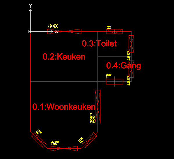
Begane grond inclusief Blocks in ProjectA.dwg
The insertion point (blue dot) of the Block should be placed on a Line of the corresponding room, at the center of the window, door, or panel. The height of the building component and the vertical distance from the floor are defined via the Attributes of the Block. You can specify the width by adjusting the x-factor. The Block has a default width of 1000mm, so the final width is the x-factor multiplied by 1000mm. For example, setting the x-factor to 0.8 will make the window, door, or panel 800mm wide.
Add a Block for each window, door, or panel in your building layer with the correct dimensions, so all your windows, doors, and panels will automatically appear in the 3D model in Elements.
Constructing the building
After completing the steps above and finishing the first layer, you can repeat these steps for the remaining layers/floors. It’s crucial that the walls (Lines) of different layers align exactly above each other. Misalignment can cause red points and surfaces in the 3D model. It’s helpful to lock and hide the already drawn layers to avoid accidental changes.
Often, different layers have similar structures with only slight variations in room layouts. In such cases, the quickest and least error-prone method is to copy the already drawn layer to the new layer. Ensure you use “Paste to Original Coordinates” so that the drawing on the new layer is placed exactly in the same position as on the original layer.
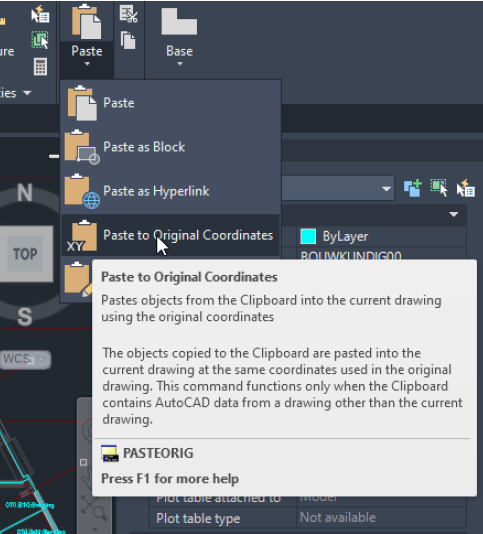
Next, you can delete the Lines of walls that do not belong to the new building layer and add new Lines where walls should now exist. Afterward, you can adjust or move the window, door, and panel Blocks as needed and correct room names and numbers.
This approach allows you to draw only the walls, building components, and room identifiers that differ, rather than starting from scratch each time. Once you’ve completed this for all layers in your building, your CAD drawing will be ready for import into Elements.
Step-by-step guide for CAD import in Elements
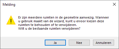
Maintaining or removing existing spaces
Start the 2D CAD import from the Geometry menu.
If there is already existing geometry in this project, you have the option to either remove it (Yes) or retain the spaces and import alongside them (No).
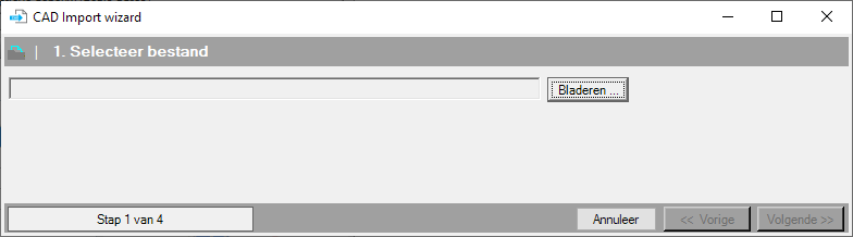
Select file
After initiating the CAD import, the above window titled CAD import appears.
Select file
In step 1, you specify which CAD drawing you want to import. Once the correct file is selected, you can click on Next.
Continue
- You can exit the wizard at any time by clicking Cancel. Exiting the wizard will terminate it and any entered data will be lost.
- You can modify data in a previous step by clicking Previous. Data from all steps will be retained.
- Once the above information has been entered correctly, proceed to Step 2 of 4: Settings by clicking Next.
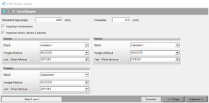
Settings
Standard layer height
Here you can enter the default floor height in millimeters that will be used for all building levels from the CAD drawing. You can adjust the height for each floor later if needed. Choose the most common floor height to minimize the need for adjustments.
Import room names
When you select this option, predefined room names and room numbers can be imported along with the data. The requirements for defining these names and numbers are explained in the CAD drawing requirements under “Space.”
Import windows, doors & panels
When you select this option, predefined windows, doors, and panels can be imported along with the data. Additional input fields labeled Doors / Windows / Panels will appear under Settings, allowing you to define the windows, doors, and panels. The requirements for drawing these blocks are explained in the CAD drawing requirements under Windows, Doors, and Panels.
Tolerance
Here you can enter a margin within which skewed CAD projects will be straightened. The default value here is set to 10 mm, meaning points that are less than 10 mm skewed above each other will be straightened during import. If you encounter red areas or points, adjusting this value may help. Setting this value to 1 can also help if your file is not importing correctly.
Settings for Doors / Windows / Panels
Windows, doors, and panels can be specified in the DWG/DXF file as blocks. The requirements for drawing these blocks are explained in the CAD drawing requirements under Windows, Doors, and Panels..
Block
Here you select from the list of existing blocks in the CAD drawing the block that represents the window, door, or panel.
Height Attribute
Here you select from the list of existing attributes in the block that determine the height.
Vert. Offset Attribute
Here you select from the list of existing attributes in the block that determine the offset, which is the height of the bottom of the frame relative to the floor.
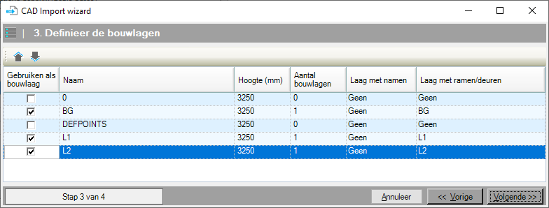
Define the building levels or floors
Use as building level
Here you select which drawing layers can actually be converted into building levels.
Name
This is the name of the drawing layer and simply lists the existing drawing layers as present in the CAD drawing.
Height
Here you define the height of each building level.
Number of building levels
Here you define the number of unique building levels. If multiple building levels have the same layout, you can choose to draw this layout once and include the building level multiple times in Vabi Elements.
Layer with names
Here you define for each building level which layer contains the room names and numbers.
Layer with windows/doors
Here you define for each building level which layer contains the blocks with windows and doors.
Preview
You will see the first drawing layer, potentially with room names and the blocks containing windows, doors, and panels.
Drawing layer
You can select the building level by directly choosing the correct building level from the dropdown menu. The 2D drawing of this building level will then appear on the screen.
<
[action]
By clicking on the < icon in the top right corner of the screen, you will navigate to the building level below it.
>
[action]
By clicking on the > icon in the top right corner of the screen, you will navigate to the building level above it.
Notifications
If errors are found in the CAD import, they will be displayed in the left column under Notifications. If you do not see the left column, you need to check the box next to Show. This will make the column with error messages appear. Common error messages include:
The line is too short to process.
If there are lines in the CAD drawing that are shorter than 20 mm, these lines will be removed during the CAD import process. Elements will display this notification accordingly. This check is built-in to prevent errors in the drawing.
You can locate these lines in the CAD drawing using the QSELECT function:
- Open the CAD drawing in AutoCAD that you want to import and that contains the error message.
- Type QSELECT in the command line.
- The Quick Select window will appear.
- Choose “Entire drawing” under Apply to.
- Choose “Line” or “(2D) Polyline” under Object type.
- Choose “Length” under Properties.
- Choose “< Less than” under Operator.
- Enter “10” under Value.
- Click OK; the line segments that trigger the error message will now be selected.
Optionally, you can delete or modify these line segments.
Note: The above function does not work with a (2D) polyline. In that case, the length is considered as the total length of the entire polyline. You need to explode a polyline to select individual segments.
Unconnected line
All intersections of lines that do not connect exactly are rounded to a grid of 20 mm to eliminate inconsistencies in the drawing and ensure perfectly closed spaces. However, if there are lines in the CAD drawing that do not connect for more than 20 mm, the above notification is given. In such cases, the space cannot be closed properly, and the associated lines are left unchanged.
This error message often correlates with the previous one. Specifically, when a line is too short to process, it is not included, resulting in an unconnected line. To resolve this issue, you need to manually correct the error in the CAD drawing by addressing the line that is too short to process.
Room already has another text
When there are multiple text lines within a room, a notification is given that the room contains multiple room names. Only the first placed text is read and used as the room name. If this is not the correct room name, you can adjust this under Step 3: Linking > Adjust Rooms, or remove unnecessary texts in the CAD drawing.
Windows, doors, or panels not on the line
In step 1 of the CAD import, you can specify which blocks should be imported as windows, doors, and panels. The prerequisite is that these blocks, with their insertion points, should be on or near a wall. If this condition is not met, the above notification will be given, and the window, door, or panel will not be imported.
DXF entity is not supported
The drawing layer to be imported from the DWG or DXF contains drawing objects that Vabi Elements does not support.
- Objects that are not supported include: Hatch, Spline, Circle, etc.
- Supported objects include: Line, Pline (Polyline), Arc, Block (for windows, doors, and panels), etc.
An Arc will automatically be segmented into straight lines during import.