HVAC
The HVAC template contains the characteristics of all heating- and cooling emission systems linked to the room. This includes a total installation concept including air handling.
Ventilation supply

Air handling
- Gebouwsimulatie
- Warmteverlies
- EPG
The air handling system to be applied in the room is indicated here. This may be e.g. an air handling unit with heat recovery and coils for heating and cooling, or a system with natural supply and mechanical exhaust. The input data can be found in the resource Air handling. The type of system is displayed next to the air handling system on the screen.
Selected system
The selected ventilation system is determined automatically based on the input values of the air handling system. The choice of ventilation system is in accordance with ISSO 51, Table 4.2 in paragraph 4.3.1.1, and ISSO 53, paragraph 4.3.3.
| Ventilation | Definition |
| System A | Ventilation with natural supply and natural exhaust |
| System B | Ventilation with mechanical supply and natural exhaust |
| System C | Ventilation with natural supply and central mechanical exhaust (for kitchen, bathroom, and toilet compartment only) |
| System C (variant) | Ventilation with natural supply ventilation and mechanical exhaust per room |
| System D | Ventilation with mechanical supply and mechanical exhaust (balanced ventilation) |
| System E | Room(s) with decentralized balanced ventilation and other rooms with natural supply and mechanical exhaust |
Publicaties
Waarden voor de luchtvolumestroom infiltratie qi in m³/s per m² buitenoppervlak
Decentral heat recovery present
- Warmteverlies
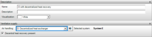
This checkbox should be enabled in the delivery template for rooms that contain a decentralized HRV unit. The supply air temperature will then be taken from the values entered for the HRV of the air handling unit. If the checkbox is not enabled, the room will be naturally ventilated. The checkbox is only available if “HRV in combination with natural supply (system E)” is selected for the air handling unit.
Control
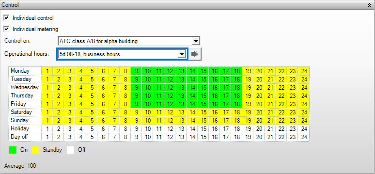
Individual control
- Gebouwsimulatie
- EPG
With this box it can be specified whether the heat emission is controlled separately. The control can be by means of a room thermostat, a thermostat valve, etc. If no control is applied the emission efficiency is multiplied by 0.8. The control is only applied for heating in housing.
Publications
Factors for determining distribution efficiencies
For building simulation, compliance with an ATG class A building also considers this checkbox to determine if the requirement for individual control is met.
Individual metering
- EPG
With this box it can be specified whether individual metering is applied. If no metering is applied, the emission efficiency is reduced by 0.10. Metering is only applied in housing with collective heating.
Publications
Calculation values for emission efficiency
Control on
- Gebouwsimulatie
The system can be controlled based on air- or comfort temperature, or by an ATG class. This control applies to the complete installation concept defined in Emissive devices.
- Air temperature is the average air temperature in the room
- Comfort temperature is the average comfort temperature in the room. Tcomfort = average of (Tair; Tradiation). If the comfort temperature differs from the air temperature, the room has either hot or cold surfaces.
- ATG class The control for ATG is carried out according to ISSO 74 from 2024.
Operational hours
- Gebouwsimulatie
A Schedule of HVAC, in which the periods of daytime- and night-time operation of the complete installation concept have been defined, is selected here.
Emissive devices
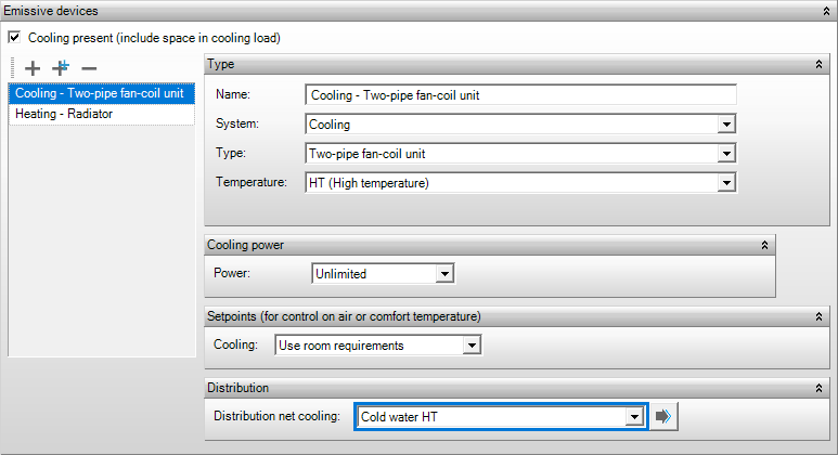
This group contains one or more emissive devices. These emissive devices are subsequently coupled to a distribution network, which in turn is linked to a generation resource (depending on the module).
A local heating-/emissive device, or an air handling unit with a heating coil (air heating) should be defined in a heated room for the heat loss calculations. No emissive devices for heating, and no air handling unit with heating coil are allowed to be specified in an unheated room.
Cooling present
- Koellast
Instead of defining emissive devices, it suffices to specify whether cooling is present in the room for the cooling load calculations. The calculation method for cooling load is based on systems in which the cooling load is absorbed by the supplied air completely.
Type
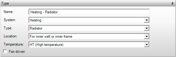
Name
- Gebouwsimulatie
- Warmteverlies
- EPG
The name of the emissive device is generated automatically based on the type and choice of device. After selecting the right type and device, this name can be modified as desired.
System
- Gebouwsimulatie
- Warmteverlies
- EPG
Choose a system in order to choose a device.
- Heating: an emissive device intended for heating the room.
- Cooling: an emissive device intended for cooling the room.
- Heating & cooling (4-pipes): an emissive device intended both for heating and cooling the room.
- Heat & cold (2-pipe, changeover): an emissive device intended both for heating and cooling the room.
- VAV-unit stands for Variable Air Volume. This can only be applied if a VAV control system is used in the air handling unit. For controlling the VAV unit, you can choose between control based on temperature, control based on CO2, or control based on both CO2 and temperature. When the air handling unit indicates “Possible to reduce per room to,” the calculation will use that minimum flow rate. If the temperature or CO2 level in a room with a VAV unit requires more ventilation, the flow rate for that room will be increased.
Type
- Gebouwsimulatie
- Warmteverlies
- EPG
Depending on the type of emission device, the following components are determined:
- For heat loss, the temperature gradient in the room is determined based on the type of heating device. In the case of multiple types of emission devices in a room, the first device entered is used.
- For building simulation, the accumulation, convection, and radiation factors are determined based on the type of device.
- For EPG, distribution and emission efficiencies are determined based on the type of device.
Heat
- Radiator
- Radiant heating panel
- Floor heating (θfloor ≥ 27°C) In ISSO 51 (2023), a distinction is made based on floor temperatures. Floor heating as the only heating system in the room. If the floor temperature is not yet known, assume a temperature > 27°C for new construction. This is calculated in GS as Floor Heating.
- Floor heating (θfloor < 27°C) See description under Floor Heating (θfloor ≥ 27°C).
- Wall heating
- CCA in ceiling
- 2-pipe fan coil unit
- 2-pipe induction unit
- Radiant tube
- Open radiant heater
- Radiant heaters
- Split unit
- Local air heating
- Local electric heating
- Local gas heating
- Local oil heating
- Local biomass device: Local heating system using biomass fuel. Biomass stoves emit less particulate matter than open fireplaces and regular wood stoves.
- Infrared (IR) panels wall mounting (new in ISSO 51 (2023), calculated as local electric heating in GS).
- Infrared (IR) panels ceiling mounting (new in ISSO 51 (2023), calculated as local electric heating in GS).
Cooling
- Chilled ceiling
- Floor cooling
- CCA
- Split unit
- 2-pipe fan coil unit
- 2-pipe induction unit
- DX cooling
Heating and cooling
- Climate ceiling
- CCA
- 4-pipe fan coil unit
- 4-pipe induction unit
- 4-pipe Climate ceiling
- 2-pipe induction unit
- Splitunit
Publications
Waarden voor Δθ1, Δθa1, Δθ2, Δθa2 en Δθv onder ontwerpcondities voor verwarmde ruimten met een maximum hoogte van 4 m
Dimensieloos afgifterendement van verwarmingssysteem in rekenzone
Factoren voor de bepaling van distributierendementen
Subtype
- Warmteverlies
Choose a subtype that is applicable with radiant heater for high spaces.
Publications
Design indoor temperature
Device
- EPG
Choice of device only possible for system “Heat’ and ‘Local air heating’,
Publications
Gas- or oil-fired boilers and air heaters
Rating Biomass
- EPG
The choice for rating biomass is only possible for the system ‘Local biomassdevice’.
- Biomass for boilers according to Activity decree
- Biomass for boilers according to the minimum burning quality specified in Annex O
- Biomass other: does not fall under appendix O
Location
- EPG
This location of the emissive device can only be specified for type ‘Radiators’ in the ‘Heating’ system.
- For external wall with Rc < 2.5 m2K/W: the radiator is placed against the façade, which has a Rc value less than 2.5 m2K/W;
- For external wall with Rc >= 2.5 m2K/W: the radiator is placed against the façade, which has a minimum Rc value of 2.5 m2K/W;
- In front of outer window with radiation shield: the radiator is placed in front of a window with a radiation shield in between;
- In front of outer window without radiation shield: the radiator is placed in front of a window without a radiation shield in between;
- In front of inner wall or inner window: the radiator is not placed against the façade or in front of an window;
Publications
Dimensionless output efficiency of the heating system in calculation zone
Location
- EPG
This location of the emissive device can only be specified for type ‘Floor heating’, ‘Wall heating, and ‘Thermal active heating’ in the ‘Heating’ system.
- External separation construction Rc < 2.5 m2K/W: the radiator is placed in the external separation construction (ground floor or façade) with a Rc value less than 2.5 m2K/W;
- External separation construction Rc >= 2.5 m2K/W: the radiator is placed in the external separation construction (ground floor or façade) with a Rc value greater than 2.5 m2K/W;
- Internal separation construction: the radiator is placed in an internal separation construction (mezzanine floor or interior wall);
Publications
Dimensionless output efficiency of the heating system in calculation zone
Temperature
- EPG
The temperature for the emissive device can be indicated here. Optionally, one can choose for heating with low temperatures, and/or cooling with high temperatures. This function is intended for low temperature systems, such as CCA.
Has exhaust for combustion gases
- EPG
It should be indicated whether the device has an exhaust for combustion gases if the emissive device has been chosen as ‘local gas heating’ or ‘local oil heating’. This parameter is used to determine the flat rate efficiency.
Publications
Dimensionless output efficiency of the heating system in calculation zone
Energy
This field indicates whether the emissive device is stoked by gas or oil. It only appears if the delivery device is a radiant heater for high spaces.
Shaft power
- EPG
The shaft power of a single split or multi split cooling device can be stated here. The nominal power is determined based on the specified shaft power in kW.
Fan driven
- Warmteverlies
This can indicate whether a radiator is fan-driven. This option is applicable to the Heat Loss Standards of 2017.
Publications
Values for Δθ1, Δθa1, Δθ2, Δθa2, and Δθv under design conditions for heated spaces with a maximum height of 4 m.
Heating and/or cooling power
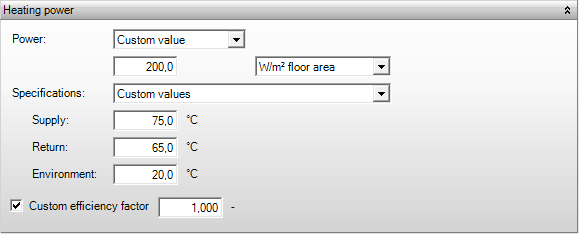
Power
- Gebouwsimulatie
This is the maximum thermal power of the heat emission device, measured in watts. If you specify this without limit, there will be no overrun hours based on the power of the heat emission device. If there are overrun hours, another component must be limited. This can be determined depending on the type of heat emission device for day and night operations.
If the supply temperature to the emission device, the return temperature from the device, and the ambient temperature of the device are the specified values, then the emission device generates the specified power. If the specified supply temperature from the distribution network and the ambient temperature in the space are different, then a different power output is delivered. This value is displayed hourly in the daily results charts and is also shown in the output tables of building simulations.
Convection factor
- Gebouwsimulatie
This is the convective part of the tactile power; the remainder is radiant heat. This convection factor only applies to ‘radiator’ emissive devices. Default value is 0,7.
| Type | 10 | 11 | 20 | 21 | 22 | 30 | 31 | 32 | 33 |
| Percentage convective | 50 | 65 | 65 | 80 | 80 | 85 | 85 | 90 | 90 |
Specifications
- Gebouwsimulatie
If the emissive device has limited thermal power; the temperature specifications can be indicated:
- Default, for which the supply-, return-, and ambient temperatures are set at default values, irrespective of whether a heating, cooling, or heating and cooling device is concerned.
- Custom values, for which the supply-, return-, and ambient temperatures are specified by the user.
Supply
- Gebouwsimulatie
This is the temperature of the supply water for the heated room. This temperature is dimensioning and hence it is not the heating curve used for the calculations. The water flow is determined based on the supply- and return temperature.
Return
- Gebouwsimulatie
This is the temperature of the water which returns from the heated room. This temperature is dimensioning and hence it is not the heating curve used for the calculations. The water flow is determined based on the supply- and return temperature
Environment
- Gebouwsimulatie
This is the average ambient temperature of the surroundings of the generator.
Custom efficiency factor
- EPG
The efficiency of heat emission from heating systems is determined according to table 14.1 of NEN 7120 on a lump sum basis. Deviation from this can be made by specifying a different efficiency, but a quality statement must be provided as justification.
Publications
Dimensionless heat emission efficiency of the heating system in calculation zone
Efficiency
- EPG
If a different efficiency, supported by a quality statement, is applied, you can specify the efficiency here.
Setpoints
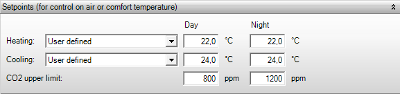
Heating
- Gebouwsimulatie
The setpoints for heat emission are defined here. If the input Similar to Room Requirements is selected, the design temperature is taken from Design temperatures in the template Room requirements.
Cooling
- Gebouwsimulatie
The setpoints for cold emission are defined here. If the input Similar to Room Requirements is selected, the design temperature is taken from Design temperatures in the template Room requirements.
CO2 upper limit
- Gebouwsimulatie
Here you define the setpoints for emission when selecting a VAV unit with CO2 control. The outdoor CO2 concentration is 420 ppm.
The standard setpoints are 800 ppm for daytime and 1200 ppm for nighttime.
For more information: https://www.vitec-vabi.com/nieuws/co2-gehalte-in-de-ruimte-berekenen-en-weergeven-in-elements/
Distribution

The Distribution which is linked to the emissive device can be selected from the library.