Distribution
The distribution network ensures the transport of heat and / or cold between the generator and the emissive device, and between the generator and the air handling unit.
For optimization of heating curves, we refer to the following standards and methods:
Publications
(Building simulation) Principles of temperature simulation calculations, physical material data
Visualisation
It is possible to visualise the distribution using a particular colour. This colour will be used in the 3D visualisation in the results section. In case you assign conspicuous colours to the various templates, this will give you a quick overview of the different templates used in the project.
Type
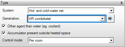
System
- Gebouwsimulatie
- Warmteverlies
- EPG
This indicates what is provided by the distribution system: Hot, Cold, or Hot & Cold. In Hot & Cold, both hot and cold water are transferred to the same emissive device (change-over) depending on the need. A distribution network is also required for a heating or cooling coil of an air handling unit, however, for this a combined Hot & Cold network cannot be specified and two separate networks (one for hot, and the other for cold) should be specified.
- Hot-water net distribution network for heating
- Cold-water net distribution network for cooling
- Hot- and cold-water net distribution network for both heating and cooling (change-over)
Generation
- Gebouwsimulatie
- Warmteverlies
- EPG
The generation configuration is chose here from the generators for heat and/or cold. Only generation configurations can be selected with generators for Hot, Cold, or Hot and Cold, depending on the specified system (Hot, Cold, or Hot and Cold respectively). The selection list is created automatically from all generation resources as specified under the resource Generation.
Other agent than water (e.g. coolant)
- EPG
Checking this box indicates another cooling agent is used other than water, such as a coolant in multi-split systems. A correction will be made to the distribution efficiency for heating and/or cooling.
Accumulator present outside heated space
- EPG
An accumulator for the heating system may be located outside the heated space in housing. If this is the case it can be indicated here and a correction on the distribution efficiency follows. This option has no effect in case of non-residential buildings.
Control mode
- Gebouwsimulatie
- Warmteverlies
Publications
Temperatures
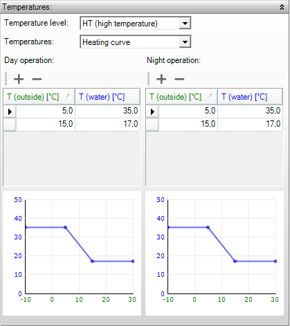
The heating curves are important for optimization and energy reduction in distribution networks.
Temperature level
- Gebouwsimulatie
- EPG
The division into HT- and LT- systems can be specified here depending on the heat generation and distribution. The generation efficiency and distribution efficiency in the EPG calculation are based on this temperature level.
- LT (Low Temperature): low temperature system. For EPG calculations, please consult NEN 7120, Tables 14.12 and 17.2.
- HT (High Temperature): high temperature system.
Publications
Calculation values for internal distribution efficiency
Calculation values for generation efficiency
Latent cooling demand (dehumidification)
Temperatures
- Gebouwsimulatie
This selection indicates the determination of the heating curve. Three possibilities are available:
- Default: the heating curve is determined using a default value, irrespective of daytime operation or night time operation, and irrespective of the outside temperature. The default temperature is 80 °C for heating, 35 °C for LT heating, 6 °C for cooling, 17 °C for HT cooling, and 18 °C for heating and cooling together;
- User defined: the heating curve has constant values as specified for daytime operation and night time operation;
- Heating curve: the heating curve is specified manually. For all values of outside temperature (Toutside) a value of the heating- or cooling water (Twater) can be specified. Separate curves can be defined for daytime operation and night time operation.
Publication
Temperatures of installations
Circulation system
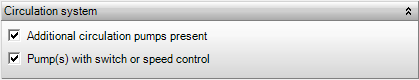
Additional circulation pumps present
Additional pumps may have been installed for the heating system. In this case, which can be indicated here, extra electric auxiliary energy is charged. By default, the auxiliary energy is charged for the main circulation pumps only.
Publications
Electrical auxiliary energy for heating (formules 14.31 & 14.33)
Pump(s) with (switch or) speed control
- EPG
In this box it can be indicated whether the main circulation pumps (and additional circulation pumps if present) are equipped with a switch and/or speed control. If this is not the case, the runtime of the pumps increases which leads to more electric auxiliary energy to be charged.
Publications
Calculation rules and values for pump power and operating time
Pipe specifications of the circulation system
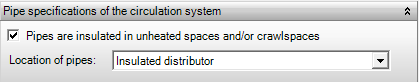
Pipes are insulated in unheated spaces and/or crawl spaces
- EPG
In this box it can be indicated whether the pipes in unheated spaces and/or crawl spaces in houses are insulated. This parameter affects the correction of the internal distribution efficiency. It also affects the distribution efficiency in non-residential buildings, which indicates whether the pipes in the system have been insulated.
Publications
Internal distribution efficiency
Location of pipes
- EPG
The structure of the distribution network for housing is specified here. This pipe structure contributes to the determination of the distribution efficiency.
- Pipes along the facade
- Insulated distributor
- Uninsulated distributor
Publicaties
Calculation values for internal distribution efficiency