Air handling
Within a project multiple air handling systems or air handling units may be defined. Within the HVAC template you may select the air handling system to link to the room. An air handling system can be defined based on multiple elements; for examples of climate systems refer to ISSO 43.
Ventilation system type
- Gebouwsimulatie
- Warmteverlies
- EPG
The ventilation system type is displayed depending on the input in the input screen for the Air handling resource; this type cannot be changed directly.
Ventilation control
- EPG
The ventilation control is displayed based on the type of ventilation system, and the regulation and control. The ventilation control is applied in the calculation of energy performance in the EPG module.
Supply
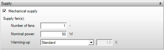
Mechanical supply
- Gebouwsimulatie
- Warmteverlies
- EPG
This box indicates whether a mechanical supply for the air handling system is present. Checking this box affects the ventilation system type in the top of the Air handling screen.
Number of fans
- EPG
This number represents the number of ventilators within the air handling unit. This input can only be specified in case the Ventilation power is determined using the detailed method in the EPG calculation. The ventilation power in the system also includes the ventilation power on room level, as is the case with fan coils.
Publications
Actually installed nominal power
Nominal power
- EPG
This is the nominal power per fan in W. In case multiple fans have been defined, the nominal power is multiplied by the number of fans. The ventilation power in the system also includes the ventilation power at room level, as is the case with fan coils.
Warming-up
- Gebouwsimulatie
- Warmteverlies
- EPG
This indicates whether the heating of air caused by the supply fan should be taken into account. The amount of heating should be specified in Kelvin.
- Default: the heating by the supply fan is taken as 1.5 K
- User defined: the heating by the supply fan can be specified between 0 and 4 K
Supply grilles
- EPG
The regulation (control) of the supply grilles can be specified in case no mechanical supply is available, and consequently the supply air is extracted from outside. The supply grilles partially determine the ventilation control type in the top of the screen, which is used for the energy performance EPG calculation.
- No control
- Wind pressure driven flow Δp ≤ 1 Pa
- Wind pressure driven flow 1 Pa <Δp ≤ 5 Pa
- Wind pressure driven flow 5 Pa <Δp ≤ 10 Pa
- Time control without zoning
- CO2 control on indirect supply in each living room, without zoning
Publications
System-related ventilation for heating and cooling – Tabel 2
Ventilation exhaust
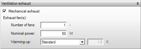
Mechanical exhaust
- Gebouwsimulatie
- Warmteverlies
- EPG
This box indicates whether a mechanical exhaust for the air handling system is present. Checking this box affects the ventilation system type in the top of the Air handling screen.
Decentralized exhaust (System C; variant)
- Warmteverlies
Checking this box (not for ISSO 2024) indicates that a variant on ventilation system C should be used in the heat loss calculations for housing. In this variant the air is extracted for each room separately (demand-controlled ventilation), rather than being extracted centrally in the kitchen, bath room, and toilet. As a result the heat loss calculations are performed with a façade which is more airtight; a lower qv,10 value can be specified.
Publications
Natural supply of ventilation air, mechanical exhaust per room
System C: Natural supply and mechanical exhaust
Residences/residential buildings that comply with the new construction requirements of the Building Decree –Tabel 4.2
Number of fans
- EPG
This number represents the number of ventilators within the air handling unit. This input can only be specified in case the Ventilation power is determined detailed for the energy performance in the EPG, as should be indicated in the Project settings.
Publications
Actually installed nominal power
Nominal power
- EPG
This is the nominal power per fan in W. In case multiple fans have been defined, the nominal power is multiplied by the number of fans.
Warming-up
- Gebouwsimulatie
- Warmteverlies
- EPG
This indicates whether the heating of air caused by the exhaust fan should be taken into account. The amount of heating should be specified in Kelvin.
- Default the heating by the exhaust fan is taken as 1.5 K
- User defined the heating by the exhaust fan can be specified between 0 and 4 K
Ventilator specifications
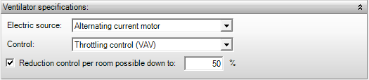
Electric source
- EPG
For the electric source it should be indicated whether the ventilators for housing are driven by an alternating current or direct current engine. This input has no effect in the case of non-residential buildings.
- Alternating current motor
- Direct current motor
Publications
Determination of nominal electrical fan power for calculation
Control
- Gebouwsimulatie
- EPG
This control specifies whether it is possible to control back the air flow volume. Back control is possible only if the fan power is specified. No back control is surcharged when the minimum fan requirements are determined using the flat rate method.
- No control (CAV)
- Throttling control (VAV). This will affect the total pipe resistance, the operating point of the device, and consequently the yield.
- Intake vane damper control (VAV)
- Blade adjustment control (VAV)
- High / low control (VAV). This regulates the fan from two positions, high or low.
- Fan speed control (VAV). This controls the number of revolutions per unit time of the fan.
Publications
Actually installed power for the entire building
Redcution control per room possible
- Gebouwsimulatie
- EPG
Check the box indicating that there is regulation. This is only possible when VAV (Variable Air Volume) is selected. When you check “Regulation possible per room up to,” and you enter, for example, 20%, then up to 20% of the specified design airflow will be regulated down.
Regulation is only possible if the actual installed ventilation capacity is specified.
For the minimum ventilation requirements determined by the standard method, no regulation is considered.
Publications
Actually installed power for the entire building
VLA methodology
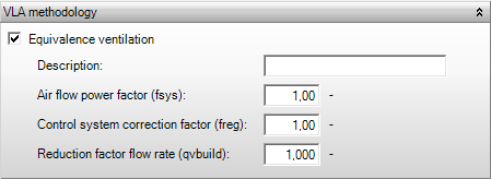
Equivalence ventilation
- Warmteverlies
- EPG
According to the VLA methodology, it is possible to apply equivalence for energy-saving ventilation solutions in residential construction. From 2024 no longer applicable. Equivalence for ventilation systems results in an adjusted correction factor for the control system \( f_{\text{reg}} \) and an adjusted air volume flow factor \( f_{\text{sys}} \). For the heat loss calculation, \( q_{\text{vbuild}} \) is important.
Description
- Warmteverlies
- EPG
Statement regarding an equivalency declaration, which will also be included in the reports.
Air flow power factor (fsys)
- EPG
Specification of the air volume flow factor \( f_{\text{sys}} \) according to the equivalency report, which replaces the standard air volume flow factor according to Table 2 of NEN 8088-1:2012.
Control system correction factor (freg)
- EPG
Specification of the control system correction factor \( f_{\text{reg}} \) according to the equivalency report, which replaces the standard correction factor according to Table 2 of NEN 8088-1:2012.
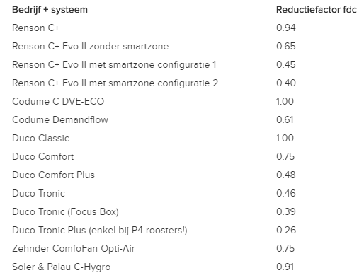
Reduction factor flow rate (qvbuild)
- Warmteverlies
Specification of the reduction factor on \( q_{\text{vbuild}} \) for a demand-controlled ventilation system according to the equivalency report, which replaces the standard value from ISSO. This has an impact on determining the connected load for heat loss ISSO 2017. The standard reduction factors for various systems are given in the image below.
Publications
Heat loss due to outside air infiltration
Actually installed capacity for entire buildings
Heating/cooling coil
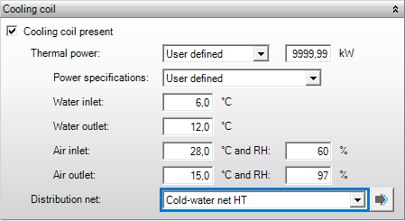
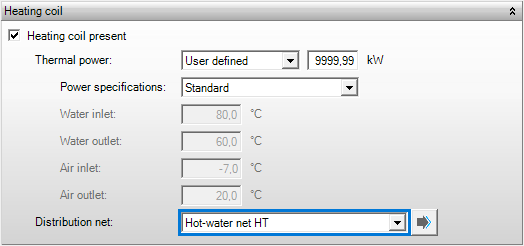
The coil specifications below should be entered according to the product data from the supplier.
Heating / cooling coil present
- Gebouwsimulatie
- Warmteverlies
- EPG
This indicates whether a heating/cooling coil is present.
Thermal power
- Gebouwsimulatie
- Unlimited; with this option it is assumed that the heating/cooling coil has unlimited power. Therefore, no maximum temperatures for the water supply and exhaust are applicable in this case;
- Limited value: the total thermal power should be specified here. This power should, at least, be consistent with flow rate as specified for the supply fan. Thus, the power of the coil as it is put in the air handling unit is concerned here.
Power specifications
- Gebouwsimulatie
The type of temperature specifications can be indicated here if the thermal power has a limited value:
- Vabi default: The default temperatures are applied, see table below;
- User defined: The temperatures can be specified manually.
| Water supply | Water drainage | Air inlet | Air output | |
| Warm | 90 °C | 70 °C | -7 °C | 20 °C |
| Cool | 6 °C | 12 °C | 27.4 °C and 80% RH | 20 °C and 98% RH |
Water inlet
- Gebouwsimulatie
This is the water supply temperature at which the thermal power is computed, and it indicates the temperature of the supply water used for cooling or heating. The water supply temperature used by the software for calculations is determined by Temperatures of the linked Distribution resource.
Water outlet
- Gebouwsimulatie
This is the water exhaust temperature at which the thermal power is computed, and it indicates the temperature of the exhaust water which remains after cooling or heating. This temperature is used to compute the flow rate through the coil.
Air inlet
- Gebouwsimulatie
This is the air supply temperature at which the maximum thermal power is determined. The air supply temperature is the outside temperature in general, but in case of heat recovery / recirculation it is computed by the building simulation.
and RH
- Gebouwsimulatie
This is the relative humidity of the supply air. The moisture conditions at the inlet are important as these conditions are mainly responsible for determining the power, and consequently the efficiency of the cooling coil when performing dehumidification.
Air outlet
- Gebouwsimulatie
This is the air exhaust temperature at which the maximum thermal power is determined. Together with the inlet temperature this is used to determine the air flow over the coil. The building simulation performs its calculations using an air heating curve.
And RH
- Gebouwsimulatie
The moisture conditions at the inlet are important as mainly these conditions determine the power, and consequently the efficiency of the cooling coil in case of dehumidification.
Distribution net
- Gebouwsimulatie
- Warmteverlies
The distribution system for this air handling unit is selected here from the systems which have been defined within the current project library. This distribution system is linked to a generation resource and a generator which can deliver heat or cold to the coil
Heat recovery
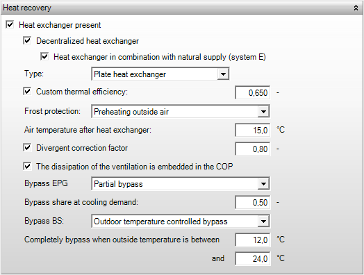
Heating the ventilation air from outside requires energy. A lot of this energy may be saved by adjusting the amount of supply air for ventilation to the need for ventilation. When applying heat recovery, the heat from the exhaust air is used to preheat the supply air. Heat recovery is only possible when both mechanical supply and mechanical exhaust are selected.
Heat recovery present
- Gebouwsimulatie
- Warmteverlies
- EPG
In this box it can be specified whether heat recovery is present.
Decentralized heat recovery
- Warmteverlies
- EPG
In this box it can be specified whether decentralized heat recovery is present. Decentralized heat recovery includes ClimaRad systems.
Heat recovery in combination with natural supply (system E)
- Warmteverlies
- EPG
If a decentralized heat recovery has been specified, in this box it can be indicated whether system E is applied. System E can be used only in housing construction, i.e. the computation of a non-residential building with system E is not possible.
Efficiency
- Gebouwsimulatie
- Warmteverlies
- EPG
The thermal, flat rate efficiency should be indicated here. A choice should be made from the predefined types according to NEN 7120.
Publications
Heat recovery efficiency.
Preheating supply air via HRV (Heat Recovery Ventilation) system
| Type of system | Thermal efficiency | Description |
| Custom value | The thermal (flat rate) efficiency may be specified manually. This value should be discussed for equivalence, and it should be rounded to a multiple of 0.05. | |
| Tube heat exchanger | 65% | A tube heat exchanger (cross-flow heat exchanger or twin-coil heat exchanger) consists of flat and corrugated sheets of aluminium or stainless steel which have been manufactured alternately flat and corrugated. Supply- and exhaust air flows along these plates. The supply- and exhaust flows are strictly separated; therefore no moisture recovery from the supply air occurs. |
| Twin-coil heat exchanger | 60% | Twin Coil |
| Cold storage with heat pump;
|
40% | |
| Heat pipe | 60% | |
| Rotating heat exchanger | 70% | A rotating heat exchanger is a slowly rotating, intermittent heat exchanger made from small aluminium tubes. It is based on a heat-accumulating element in the shape of a wheel which is alternately run through supply and exhaust air. The thickness of the heat exchanger determines the heat capacity.
The heat exchanger is rotating at a speed ranging from 1 to about 10 revolutions per minute. The temperature of the supply air can be kept reasonably constant by varying the angular velocity of the heat exchanger. The hot exhaust air is run through the aluminium tubes which take on the temperature of the exhaust air. The rotating wheel then runs the tubes through the supply air. This supply air is heated by the hot aluminium tubes. This same heat exchanger can be applied in offices with a cooling system to precool the hot supply air from outside using the relatively cool inside air during summer.
|
| Counter flow heat exchanger | 75% | A counter flow heat exchanger, or tilt valve system, consists of fans, a tilt valve, and two cassette cases with aluminium cassettes for heat storage. Air from the building is blown outside through a cassette box by means of a valve housing. The aluminium cassettes in the cassette case ensure that the heat from the suctioned air is stored in the cassettes. After a while the valve in the valve housing tilts, after which the cold outside air is led inside through the heated cassettes. The stored heat in these cassettes warms up the outside air. Efficiencies of 90% are possible with this system and also moisture recovery is a possibility. A combination is possible with adiabatic cooling, in which the temperature drops due to atomization.
Besides heat recovery from hot ventilation air during winter, cold recovery in a cooled building is possible in the same way from the relative cold inside air during summer. |
| Kantherm heat exchanger | 90% | The Kantherm heat exchanger recovers heat, cold, and moisture from the exhaust air depending on the season. During winter the Kantherm recovers both heat and moisture, and in summer it can ventilate freely (free cooling) or recover cold. |
Moisture recovery present
- Gebouwsimulatie
Choice option when rotating heat exchanger or Enthalpy Heat Exchanger are present.
Frost protection
- Warmteverlies
Choice option in heat loss when heat recovery type is not an Enthalpy Heat Exchanger (100% efficiency).
The options are:
None / unknown (100% outside air) – ISSO 2017 calculates without Heat recovery; ISSO 2023 calculates with 75% efficiency.
Fan-speed reduction / temporary unbalance (100% outside air) -ISSO 2017 calculates without Heat recovery; ISSO 2023 calculates with 75% efficiency.
Preheating outside air – Heat Recovery is included
This option is applicable for the Heat Loss Standards of 2017: an input field for the temperature after heat recovery will appear. If the option is applied for ISSO 51 2023, then a field for the temperature after preheating before heat recovery will appear.
Publications
Air temperature after recovery
- Warmteverlies
The air temperature after heat recovery is indicated here. This value is used in the heat loss calculations. If only heat recovery is present in the system, this temperature is blown into all rooms, unless heating by the ventilator is specified, which is not included in the efficiency of the heat recovery. In the latter case the heating of the ventilators is added to the temperature after heat recovery.
Publications
Specific heat loss due to ventilation
Temperature after preheating for heat recovery
- Warmteverlies
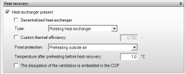
The temperature entered here is the temperature of the air before the heat recovery system if “Preheating outside air” is selected for Frost Protection in ISSO 51 2023. This temperature is used as the input to the heat recovery system, thereafter the supply air temperature is determined based on the efficiency of the heat recovery system. The preheating can be done electrical or using the exhaust air. The capacity to heat the air from outside temperature to the temperatuur in the checkbox (in the picture 1°C) is not added to the calculated heatcapacity but the value is mentioned seperately in the report.
Divergent correction factor
- EPG
By default, a correction factor of 0.8 (practical efficiency correction) is applied on top of the heat recovery efficiency. This correction accounts for air- or heat leakages. In case you diverge from the standard correction factor of 0.8, this should be supported by measurements or calculations according to NEN 8088, Appendix C.
Publications
![]()
Determination of the practical efficiency correction factor of an HRV (Heat Recovery Ventilation) system
Insulated supply channel
- EPG
Specification of insulation for the duct section located within the building envelope.
Publications
![]()
Bepaling van de praktijkrendementcorrectiefactor van een WTW-installatie
Constant volume control HRV (Heat Recovery Ventilation)
- Warmteverlies
Specification of whether the HRV system has a constant volume control to compensate for pressure changes by adjusting the supply and exhaust fans; the control must be active at all ventilation switch settings.
Publications
![]()
Bepaling van de praktijkrendementcorrectiefactor van een WTW-installatie
The dissipation of ventilation is embedded in the COP
- Gebouwsimulatie
- Warmteverlies
- EPG
If the dissipation of ventilation (heating of the ventilation air by the ventilator) is included in the efficiency of the heat recovery, the specified heating of the ventilator (if available) is not surcharged any more.
Publications
![]()
Central air handling – Calculation values
Bypass EPG
- EPG
This option allows you to specify whether the heat recovery uses a (partial) bypass. If this is the case the cool outside air can cool the building during the summer months without being post heated by the heat recovery. This will have a beneficial effect on the EPC.
Publications
![]()
Purge ventilation in residential construction
Bypass GS
- Gebouwsimulatie
Here you can indicate whether the heat recovery uses a bypass. A bypass allows cool outside air to cool the building during summer months without being reheated by the heat recovery, which has a favorable effect. The options are:
1. Without bypass
2. Supply air temperature controlled bypass – the bypass is used to achieve the desired supply air temperature as efficiently as possible.
3. Outdoor temperature controlled bypass – the bypass is used based on specified outdoor temperatures.
Newsletter item: Bypass in building simulation
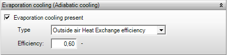
Evaporation cooling (Adiabatic cooling)
Evaporation cooling present
- Gebouwsimulatie
With the adiabatic cooling option, it is possible to perform calculations that incorporate the use of adiabatic cooling. Adiabatic cooling can be achieved in various ways.
Type
- Gebouwsimulatie
Here you can specify the type of evaporative cooling present when evaporative cooling is selected. Currently, the following options are available:
- Outside Air Heat Exchange efficiency: Indirect Evaporative Cooling, this type is based on cooling the outside air through humidification. Using a heat exchanger, the supply air for the air handling unit is pre-cooled with the chilled saturated outside air.
- Oxycom Dew Point: This is an efficient, compact, and lightweight heat exchanger that combines (dew point) cooling with high-efficiency heat recovery. The technology used here is the OXYCELL technology. This technology provides cooling in a completely natural way and does not use refrigerants.
Efficiency
- Gebouwsimulatie
When the type Outside Air Heat Exchange is selected, you can specify the efficiency of the system here.
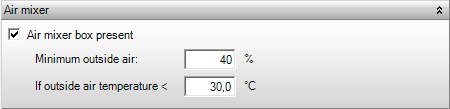
Air mixer
Air mixer box present
- Gebouwsimulatie
- EPG
In this box it can be specified whether air mixing, or recirculation, is applied in the system. The recirculation is only taken into account in the energy performance calculation EPG if these calculations are performed based on the actual installed ventilation power. This means that the recirculation is not taken into account for air flows according to the minimum ventilation requirements.
Minimum outside air
- Gebouwsimulatie
- EPG
If air mixing is applied, the percentage of supply air which consists of fresh outside air (not recycled air) can be specified in this field. The remaining supply air will be extracted from exhaust air. The fraction of fresh outside air should comply with the minimum ventilation requirements for the energy performance calculation EPG.
If outside air temperature <
- Gebouwsimulatie
The maximum outside temperature below which the outside air is allowed to be mixed with recirculation air is specified here.
Humidification / dehumidification
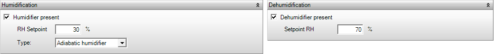
Humidifier/dehumidifier present
- Gebouwsimulatie
- EPG
This box allows you to indicate whether a humidifier/dehumidifier is present and should be taken into account in the calculations. The specifications of the dehumidifier can be indicated in this screen. The effectiveness of the coil is determined based on the thermal power delivered at a given water supply temperature, air supply temperature, and moisture conditions. The software is able to determine the maximum thermal power under various conditions (air volumes, supply temperatures, moisture content, etc). The true air volumes (in the given conditions) are specified from the supply fan, and the supply temperatures from the heating curves for water and air. The cooler/ dehumidifier is controlled based on temperature and moisture content.
Setpoint
- Gebouwsimulatie
The setpoint determines when the system must humidify/dehumidify the air. This part is activated when the relative humidity is below the setpoint for humidification and above the setpoint for dehumidification. The moisture conditions are important as these determine the effectiveness of the cooling coil for a large part in case of dehumidification.
Publications
Design Criteria for humidity
Type
- Gebouwsimulatie
- EPG
The type of humidifier is only applicable for EPG calculations (Source: SenterNovem). If the selected type is the electricity-driven steam vaporizer, then the energy source will be electricity in the EPG calculation. For the other types, the required energy is provided by the heating system and whatever generator is specified for.
- Gas-driven steam vaporizer: Steam is blown into the air through a tube with holes. The steam is generated in one or more small gas boilers by the evaporation of water. These devices heat up water using a heating element driven by gas. The obtained vapour is added to the air in a controlled way.
- Electricity-driven steam vaporizer: Steam is blown into the air through a tube with holes. The steam is generated in one or more small electric boilers by the evaporation of water. These devices heat up water using a heating element driven by electricity. The obtained vapour is added to the air in a controlled way.
- Ultrasonic humidifier: In this method, water is atomized by means of ultrasonic vibrations in aerosols. The air in the channel in which these vibrations take place absorbs these aerosols quickly. The movement of air is achieved using a ventilator. The relative humidity can be kept at a high level with this method.
- Adiabatic humidifier: The humidifier works through the expansion and contraction of air; literally adiabatic means: without heat exchange with the environment. So no heat exchange occurs in an adiabatic process, but rather compression leads to heating and expansion to cooling.
Moisture recovery present
- Gebouwsimulatie
- EPG
In this box it can be indicated if moisture recovery is present. If this is the case, a reduction to the energy need for humidification is surcharged.
Publications
![]()
Determination of energy use for humidification – calculation rules
Air control
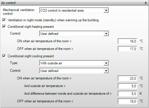
Mechanical ventilation control
- EPG
The mechanical ventilation control can be specified here. The Ventilation control type in the top of the screen is determined based on the mechanical ventilation control. This Ventilation control type is applied in the energy performance calculation EPG.
- No control
- Time control without zoning
- Time control with two or more zones,
- CO2 control exhaust only
- CO2 control in residential area
- CO2-control with two or more zones,
- CO2 control in residential area with cooker
Publications
![]()
System-related ventilation for heating and cooling needs – Tabel 2
![]()
Purge ventilation in the residential building category
Ventilation in night mode when warming up the building
- Warmteverlies
In buildings with mechanical supply of ventilation air, the calculations can take it into account when the ventilation is in night mode when warming up the building. During this night mode the ventilation performs at 50% power in housing and it is inactive in non-residential buildings. The power required for (possibly) warming up the ventilation air has been charged already. This power is not used during heating of the building (partly for housing), therefore, it can be used to heat up the building. As a result, the required power for heating of the ventilation (partly for housing) air is subtracted from the power to be installed in the room. In heat loss calculations, it is always safer not to work with the ventilation in night mode when warming up the building.
Publications
Allocable surcharge for operational limitation
Allocable surcharge for operational limitation
Conditional night heating present
- Gebouwsimulatie
The central air handling unit is controlled for conditional nighttime heating based on conditions in the Control Room. If the room temperature in the space to be calculated falls below the activation temperature, nighttime heating will activate. The system will then switch to the airflow rate for conditional nighttime heating. Conditional nighttime heating with ventilation air is only possible if:
- An airflow rate for conditional nighttime ventilation is specified under Ventilation.
- The airflow rate for conditional nighttime ventilation is greater than the airflow rate for (normal) nighttime ventilation.
- A nighttime mode is set in the emission template.
If conditional night heating present is selected, the nighttime heating curve will be followed. These heating curves, as well as the nighttime mode for both Distribution and Air Handling, must be specified.
ON when air temperature of the room <
This is the room temperature at which the air heater and fans turn on. When the Control Room temperature is colder than this temperature, nighttime heating will activate. This is also known as the activation temperature. This setting only becomes visible if conditional nighttime heating is selected.
OFF when air temperature of the room >
\[°C\] Standard 17 °C GS
This is the room temperature at which the air heater and fans turn off. When the room is warmer than this temperature, nighttime heating will not activate. This is also known as the deactivation temperature. This setting only becomes visible if conditional nighttime heating is selected.
Conditional night cooling
- Gebouwsimulatie
In this screen you can specify whether the night cooling is provided by the intake of additional air and/or by the central air cooler. The central air handling system is controlled based on the conditions in one of the rooms for conditional night cooling. The night cooling is activated when the room temperature of this room is below the switching temperature and the temperature difference (between inside and outside) is larger than specified. In this case the flow rate for conditional night cooling is applied. Conditional night cooling with ventilation air is only possible if:
- A flow rate for night mode has been specified in the Ventilation template;
- The flow rate at conditional night ventilation is greater than the flow rate at (normal) night ventilation.
ON when air temperature of the room >|url=lbk.regeling.vwnachtkaan1.htm
[° C] Standard 23 °C BS
This is the room temperature at which the air cooler and ventilators are activated. Night cooling will be activated when the room temperature is above this specified temperature. This is also called the activation temperature. This setting only becomes visible if conditional night cooling has been chosen.
And outside air temperature >|url=lbk.regeling.vwnachtkaan2.htm
[° C] Standard 5 °C BS
This is the outside temperature at which the air cooler and ventilators are activated. Night cooling will be activated when the outside temperature is above this specified temperature. This setting only becomes visible if conditional night cooling has been chosen.
And difference between inside and outside air temperature >|url=lbk.regeling.vwnachtkaan3.htm
[K] Standard 5 K BS
Conditional night cooling may only be activated if the difference between the room temperature and the outside temperature is greater than a specified minimum value. The room temperature is considered at the end of the previous hour. This setting only becomes visible if conditional night cooling has been chosen.
OFF when air temperature of the room <|url=lbk.regeling.vwnachtkuit.htm
[° C] Standard 18 °C BS
This is the room temperature at which the air cooler and ventilators are deactivated. Night cooling will not be activated when the room temperature is below this specified temperature. This is also called the deactivation temperature. This setting only becomes visible if conditional night heating has been chosen.
Air Distribution
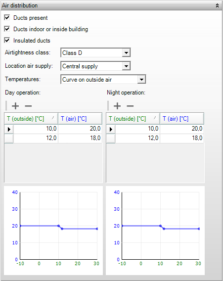
Ducts present
- EPG
This box indicates ducts are present for the ventilation system. In case of a central system with air ducts a correction is applied to the chargeable ventilation capacity depending on the airtightness class of the ducts.
Ducts indoor or inside building
- EPG
In this box it can be indicated whether the ducts are indoor or inside the building. This is used in the energy performance calculation EPG for housing; in case of non-residential building this option does not affect the results. This box only appears when ducts are present as well as a heating coil in the system. The distribution efficiency for the heating system is determined partially based on this checkbox.
Publications
![]()
Calculation values for internal distribution efficiency
Insulated ducts
- EPG
In this box it can be indicated that the ducts have been insulated, which affects the energy performance EPG calculation both for housing and non-residential buildings. This box only appears when ducts are present as well as a heating coil in the system. The distribution efficiency for the heating system is determined partially based on this checkbox.
Publicaties
![]()
Calculation values for internal distribution efficiency
Airtightness class
- EPG
The air tightness class of the ducts in the system can be specified here. This is only required if ducts are present. Depending on the specified class, a correction is applied to the ventilation capacity to be accounted for, as shown in Table 4 of NEN 8088.
The allowable air leakage of components is related to air tightness classes (A, B, C, and D) according to the NEN-EN 1751 standard. Class D is the most airtight. To achieve the desired air volume, a fan will need to blow more than 20% more air into a duct that meets air tightness class A than into a duct that meets air tightness class C.
Publications
![]()
Correction for air leakage in ventilation ducts, tabel 4
Location air supply
- EPG
In case of housing, it is indicated whether a central supply or a supply at the facades is applied. This distinction is used in the energy performance calculation. The location of air supply is only asked for if air ducts are present and a heating coil has been specified. The distribution efficiency of the heating system is determined partly based on the location of air supply.
Publications
![]()
Calculation values for internal distribution efficiency
Temperatures
- Gebouwsimulatie
- Warmteverlies
The heat curves are important in the air handling unit to optimize the energy reduction. In temperatures, the heating curve is determined, which can be done in one of the following three ways:
- Default; In this setting a constant temperature of 18 °C is applied in both daytime and night time operation;
- Constant: In this setting a constant, user specified, temperature is applied in both daytime and night time operation;
- Curve: The complete heating curve is defined manually. For all values of outside temperature (Toutside) a value of the heating- or cooling water (Twater) can be specified. Separate curves can be defined for daytime operation and night time operation.
Publications
Energetically optimal heating and cooling curves for air-conditioning systems in office buildings