Settings
![]()
You can adjust the drawing screen settings in the Settings screen. You have the option to modify the ground level height and the north orientation.
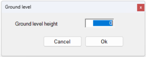
Ground level
![]()
The ground level can be adjusted. With these settings the height of the grid is changed in relation to your building
This function has influence on the automatic limitation of the façade. When a construction part is halfway under ground level
The building height used in templates will automatically be adjusted when the ground height is adjusted.
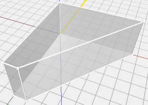
Move Axis
![]()
With Move Axis, you can shift the axis relative to the default base X, Y, and Z directions.
In the menu bar, click on the Move Axis function in the settings window.
Click in the geometry at the location where you want to place the origin of the coordinate system.
Click in the geometry to determine the direction of the X-axis.
Click in the geometry to determine the direction of the Y-axis; the Z-axis is now automatically fixed and the coordinate system is placed in the new location.
Click in the geometry to determine the direction of the Y-axis; the Z-axis will now be automatically fixed, and the coordinate system will be placed in the new location.
Reset axis
![]()
With Reset Axis, you return the X, Y, and Z axes to their original positions.
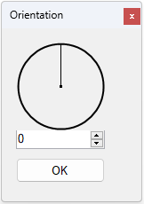
Orientation
![]()
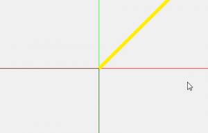
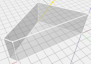
The orientation (decimal degrees) indicates the model’s orientation relative to the north. This setting changes the yellow line on the ground plane in the drawing.
This function also affects the structural data of the building if the Input is set to extended. The constructions are determined per orientation.
The yellow line represents the north arrow in the 3D view.