BIM Connect
The BIM import wizard is designed to facilitate the process of importing and converting a 3D drawing into a 3D geometry that Vabi Elements uses for its calculations. It employs a step-by-step approach. The IFC versions IFC 2×3 and, if applicable, IFC4 can be imported. Starting from version 3.2, it’s possible to perform a CAD import while retaining the geometry already present in the project. From version 3.3, it’s also possible to import gbXML files. However, this function might not work perfectly due to incorrect exports from Revit.
You can invoke the BIM import in two ways:
- After completing a New Project wizard, you’ll be prompted with five options, and you can choose to start the BIM import wizard.
- In the main menu under Wizards, you can find the BIM Import button.
IFC Import Example Videos
The video below provides a step-by-step explanation of how to prepare a BIM model (in Autodesk Revit) for importing into Vabi Elements.
When problems occur during the above method, there is an alternate method in the video below. The program will load the geometry, however, without doors and windows.
General requirements to the IFC file
Supporting file formats
The version of the IFC file should be either IFC 2×3 or IFC4. Older IFC file formats are not supported.
Size of the file
- Since Vabi Elements uses a lot of memory to prepare BIM projects for the calculations, we found that the computer and software may run into their limits. As a result Vabi Elements can crash in steps 2, 4, or 5.
- Please consider a limit of approximately 500 rooms and/or 500 windows. Other components, such as pipes, air ducts, etc. are not relevant in this respect.
- The exact limit depends on the configurations of hardware and software, and on the IFC import settings. In case you run into a limit frequently, please contact Vabi Software. We may be able to help you to improve the performance of your computer.
IFC classes
The IFC should contain the following classes:
- Spaces (ifcSpace);
An IFC model without Spaces cannot be imported. This also holds for rooms without a “Space” definition. The Spaces are used in Vabi Elements to identify the rooms. It ensures that the list of rooms corresponds correctly to the BIM model. Note that Spaces may not be overlapping. Spaces may include multiple classes, such as zones, areas, rooms (architectural), and spaces (installations). These classes may overlap. If you import all classes at once, the spaces may overlap and errors may develop. We advise to choose one class in the IFC, such as the rooms which appear in the list of rooms in the BIM model.
The surface area and volume of the space should be practically correct. Spaces which are lower or higher than the rooms are imported wrong. - Walls (ifcWall, ifcWallStandardCase), slabs (ifcSlab) and roofs (ifcRoof);
The centre point dimensions of the rooms are determined using the walls, slabs, and roofs. If the software cannot find a wall, these centre point dimensions cannot be determined and the outside air flows into the rooms. As a result all walls become exterior walls and, consequently, the calculations are incorrect.
The IFC file may contain the following classes:
- Windows (ifcWindow), doors (ifcDoor) and curtain walls (ifcCurtainWall);
Windows, doors, and curtain walls are recognized and imported as subfaces in the walls, slabs, and roofs. Naturally, it is possible to import an IFC model without rooms, doors, and curtain walls. - Columns (ifcColumn);
Columns are not required, but they may exist in the BIM model. If a column is present, it will be combined with the room in which it is in general.
Additional IFC classes are not imported for the building programs of Vabi Elements.
In case of an IFC export, it should be made sure the Architectural model is exported at least. The technical installation model does not contain the above IFC classes most of the time.
Autodesk Revit
The BIM Connector of Vabi Elements allows you to import a BIM model, created in Autodesk Revit Architecture or Autodesk Revit MEP, into Vabi Elements, using an IFC-file.
To guarantee a seamless import process, we describe the following points of attention for Autodesk Revit.
Roadmap for the modeller
- Check whether all Rooms, Spaces, or Areas have been defined in the Revit-file.
- Check whether the slab- and wall construction have been modelled correctly. See Section 3.2.
- Check whether the windows and doors have been modelled correctly. See Section 3.3.
- Check whether the Volume Computations in Areas and Volumes have been configured in the Revit-file. See Section 3.4.
- Check whether all Rooms, Spaces, or Areas are correct. See Section 3.5.
- Export the IFC file, by using an IFC from Vabi. See Section 3.6.
The IFC file is now ready to be imported into Vabi Elements.
Slab and wall constructions
Slabs and walls can be modelled in two ways:
- A wall/slab is a single object. For example, an exterior wall may be single wall, consisting of multiple material layers. See figure below.
- A wall/slab consists of multiple objects. For example, an exterior may consist of multiple walls, each of which consisting a fraction of the material layers.
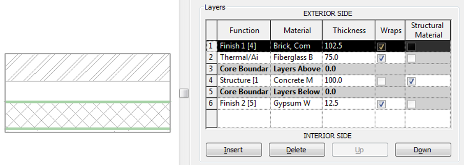
Materiaallagen in Revit
It is essential to use the first method to model walls in order to obtain a correct handling of the centre point determinations, to be able to connect rooms such that an interior wall is recognized, and to be able to interpret the Rc-value of the wall.
If the second method is used to model walls, it is possible to import the project. However, it is more likely the interior walls are not recognized, which would mean all rooms would border to the outside with their interior walls. Additionally it is more likely exterior walls are not recognized which means the dimensioning of the room will contain errors. So, the second method of modelling walls can cause a lot of problems.
The same principle holds for slabs as well.
Windows and doors
Windows and doors should be placed in a wall, slab, or roof. If the rooms are not positioned in the main construction, the IFC will not recognize the relation between the window or door with the wall, slab, or roof. This relation is required to know the face in which to position the window or door.
Autodesk Revit checks whether the standard windows or doors are positioned in a wall. If a custom family is created for windows or doors, an opening should be defined when setting up this family.
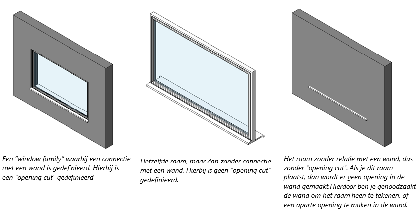
When applying the windows and doors correctly, the IFC file gets a correct internal relational structure among the windows/doors, the opening, and the wall. See the scheme below.

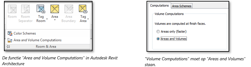
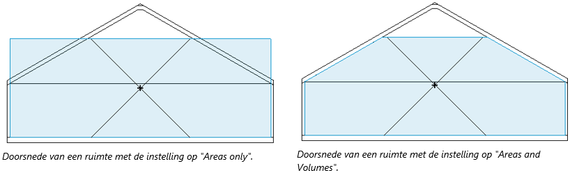
Volume Computations
In order to obtain a correct definition of the rooms, areas, and spaces the function Area and Volume Computations should be set to Areas and Volumes. It is important to check this setting, as it is set to Area’s only (faster) by default when starting a new Revit project.
Rooms, Spaces or Areas
Rooms should be specified to be recognized in a Revit model. This is possible using the following objects:
- Rooms using Autodesk Revit Architecture
- Spaces using Autodesk Revit MEP
- Area’s using Autodesk Revit Architecture & MEP
Enclosed rooms
If the warning Room is not in a properly enclosed region appears when positioning a room, it means the room is not enclosed correctly. Vabi Elements will not be able to recognize such a room.
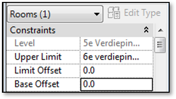
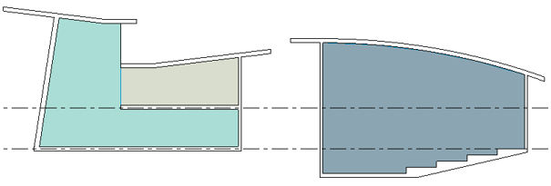
Room heights
A room should not be too high, but certainly not too low either. The best course of action is to set the Upper Limit of a room at the top side of the storey slab.
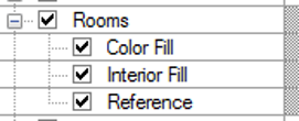
Make Rooms, Spaces or Areas permanently visible by following these steps:
- Navigate to Properties (View) > Visibility/Graphics
- Open the tab Model Categories
- Check the box Interior Fill in Room, Space or Area.
- Click OK
A Vabi View Template of the settings above can be defined in Menu > View > View Templates > Manage View Templates.
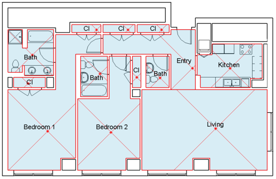
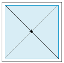
Applying this visualisation to a cross section function allows you to check whether the rooms have been specified correctly in a simple way.
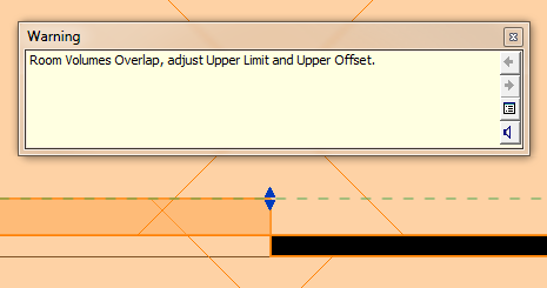
Multiple rooms
It is possible that multiple Rooms have been defined in a room, which will cause the warning shown below to appear. If this warning is displayed, please make sure multiple rooms do not occur.
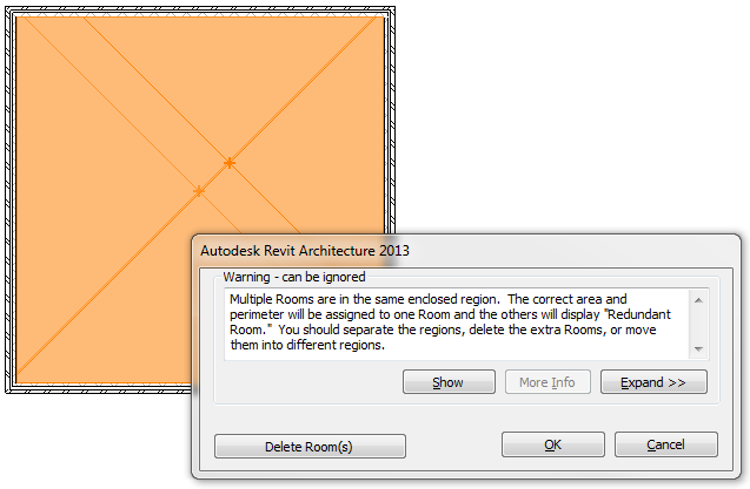
Multiple rooms are not deleted in Vabi Elements BIM Connect, which results in an erroneous geometry. However, multiple rooms can be recognized in Vabi Elements as a completely dark-grey room. The function “highlight interior building parts” should be activated in this case.
Overlapping rooms
A room is cut off at walls, slabs, and roofs. If an empty space, a stairwell, an elevator shaft, or something alike is located above the room, the underlying room is not cut off. Its height will then be determined based on the top level of the space. You should not let these empty spaces and stairwells to overlap each other. In other words, please make sure the height has been specified correctly.
Vabi Elements BIM Connect will try to repair overlapping rooms by subtract the first from the second room. The software determines the room for which the geometry is not modified, and the room for which the geometry is modified.
Compound ceilings
In general, compound ceilings are taken into account during a BIM import. If no room or space (e.g. a plenum) is located above the compound ceiling, the height of the rooms is increased until it hits the top side of the slabs in the room above. This is done since the calculations in Vabi Elements require all rooms to be fixed together.
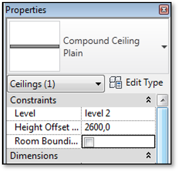
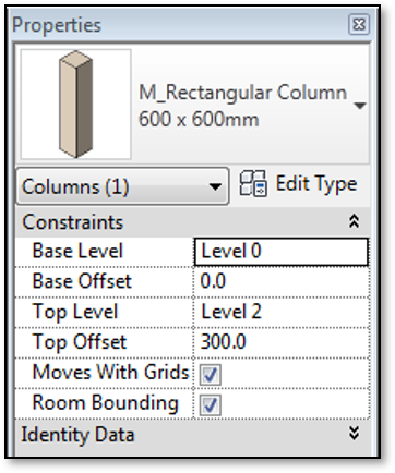
Room bounding aanzetten
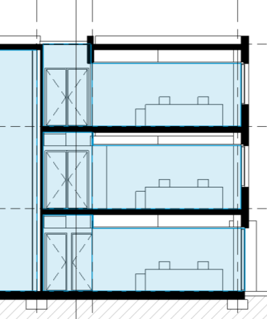
Niet aanbevolen
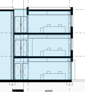
Aanbevolen
Columns
If a column occurs it will be combined with the room in which it is located. If you experience problems when importing columns, you can switch of “Room bounding” for columns.
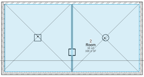
Aanbevolen
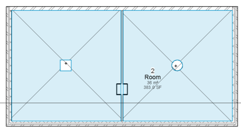
Niet aanbevolen
Het aan- en uitzetten van “room bounding” van een element.
IFC export in Autodesk Revit
The following steps can be followed to obtain a correct IFC export from Autodesk Revit:
- Check all items above as described in Sections 3.2-3.5. If the BIM model has been defined correctly, the IFC export can be started.
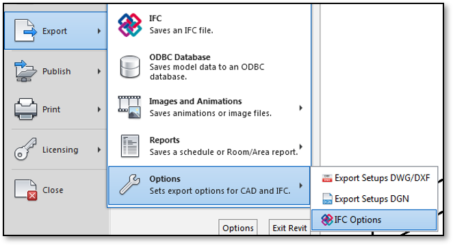
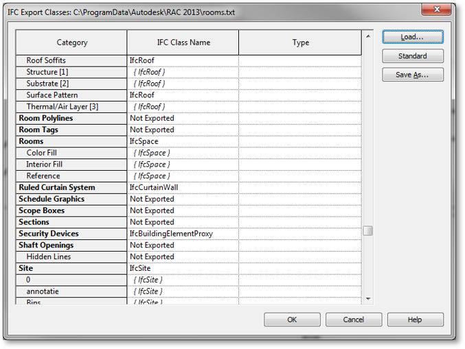
- Click on file > export > options > IFC options, see Figure 45. A sub-screen “IFC export classes” will appear now, see Figure 46.
- Make sure to check the items in the list below:
(These settings are usually defined correctly for architectural BIM models)- Rooms, Spaces or Areas should have an IFC Class Name “IfcSpace. Note: only one of these three options can be specified. The other two should be set to “Not Exported”.
- Curtain Systems should have IFC Class Name “IfcCurtainWall”.
- Doors should have IFC Class Name “IfcDoor”.
- Slabs should have IFC Class Name “IfcSlab”.
- Roofs should have IFC Class Name “IfcRoof”.
- Windows should have IFC Class Name “IfcWindow”.
- Walls should have IFC Class Name “IfcWall”. The same holds for Walls/Interior, Walls/Exterior, and Walls/Foundation.
- All underlying settings of the classes mentioned above should get the same name as the class, enclosed with {…}. This is defined automatically by Autodesk Revit.
- Hint: try to prevent “IfcBuildingElementProxy” as IFC Class Name as much as possible. This is a class type “other”, therefore, it does not belong to a standard class.
- When the IFC Export Classes have been verified, the IFC export can be started.
- Click on file > export > IFC (Saves an IFC file.), see Figure 45. A new sub-screen will appear now.
- Assign a name to the IFC file, e.g. the same as for the rvt-file.
- Click on Save
The IFC file is created now. It is possible Autodesk Revit is not operable a little while (it seems as if Revit is crashing). This can take some time, depending on the size of the Revit model.
By default, Rooms, Spaces and Areas are converted into the object IfcSpace. If the BIM model consists of Rooms, Spaces, and Areas, problems arise when importing it into Vabi Elements.
Vabi IFC Layer files
The IFC export may not work, for example because the class structure of the layers is incorrect, or because the IFC options were not set correctly. In this case, the standard IFC layer files can be used. Three layer files were created by Vabi for the IFC export from Autodesk Revit to Vabi Elements. These text files can be imported in Autodesk Revit, such that the IFC export options for Autodesk Revit are set correctly immediately.
If you want to make use of these IFC layer files, they can be requested at elements@vabi.nl.
- If you want to export Rooms, please choose the file txt.
- If you want to export Spaces, please choose the file txt.
- If you want to export Areas, please choose the file txt.
Note: Rooms, Spaces, and Areas cannot be exported in an IFC file all at once.
Installing the IFC layer file in Autodesk Revit:
- Click on file > export > options > IFC options, see Figure 45. A new sub-screen “IFC export classes” will appear now, see Figure 46.
- Click on Load…
- Select one of the files mentioned above.
- Click on Open
- Click on OK
Roadmap IFC-import
Select file
In step 1, you specify the IFC file you want to import. If a valid file is selected, the wizard will automatically proceed to the next step.
File control
The IFC file is being checked for accuracy.
Depending on the size of the IFC model, this process might take some time. Please be aware of a maximum loading time of 30 seconds.
If the file is validated successfully, the following file information will be displayed:
| Description | Description of how the IFC schema is represented. This is usually “CoordinationView.” For more information, refer to the BuildingSmart website. |
| Implementation level name | The name of the design, the name of the project. This is typically the file name and the original directory. |
| Time stamp | The date when the IFC file was created. |
| Author | The name of the person who created the project. |
| Organization | The organization that created the project. |
| Preprocessor Version | The name of the software used to create the IFC. |
| Originating System | The version of the program used to create the IFC. |
| Authorization | The person or organization that provides authorization for the project. |
| File Schedule | The IFC version of the IFC file. This is usually IFC2X3, although IFC4 is also possible. |
When the file is not correct, various error messages can indicate what needs to be adjusted:
BIM002 No solids and no spaces found in the file. File itself does not have to be incorrect. Check if the IFC file contains one or more spaces with the class IfcSpace. (Refer to IFC classes.) An IFC file must contain spaces. Spaces without IfcSpaces cannot be imported.
BIM003 File could be opened, but according to the header, the schema/version is not supported. Check if the file is correct. Is it an IFC file? Does the IFC file have the correct structure? (Refer to IFC file requirements.)Bovenkant formulier
Settings
Geometry options
You can choose which way you would like your rooms to be imported:
- Standard import; the rooms are imported as they are scanned into IFC
- Import the floors as rooms: alle rooms on one floor. This choice might be nice when you have a lot of rooms and you want to make a simple shell calculation.
Importing windows or doors
In this step, you can choose whether the windows and doors should be imported or not. Yes or no. When this checkbox is unchecked, no windows and doors will be imported. Only the rooms will be visible in the geometry of Vabi Elements.
If you are in an early design stage, you can draw the windows and doors yourself in Vabi Elements using a percentage approach. This allows you to consider the size and placement of the windows in relation to the energy requirements and comfort of the room.
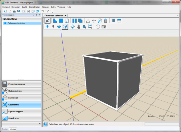
Preview
The IFC file is displayed in 3D, including a tree view of all the windows, doors, walls, floors, ceilings, and rooms. This step allows you to verify if the 3D model aligns with what you intend to import.
You can manipulate the model using the standard mouse controls of Vabi Elements (zooming and rotating with the middle mouse button). Depending on the size of the IFC model, this might take some time. Please be prepared for a maximum loading time of 5 minutes.
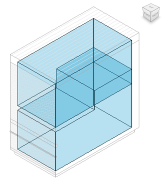
Selection of Rooms
Optionally, in the tree view, you can select one or more rooms. This allows you to choose which rooms you want to import, leaving out or simplifying the import of other rooms.
- If you chose “Standard import” as Geometry options in step 3, only the selected rooms will be imported. The other rooms will not be imported.
- If you chose “Import floors as rooms” as Geometry options in step 3, the selected rooms will be imported, and the other rooms will be imported together as floors.
When you select a room in the tree view, it will be highlighted in blue in the 3D display. Refer to the image below. For multi-selection, you can use the CTRL and SHIFT keys. The behavior of these keys in the list is in line with Windows conventions.
Result
After the project is imported into Vabi Elements, all rooms, walls, floors, windows, etc. are placed in their correct locations.
Depending on the size of the IFC model, this process might take some time. Please be prepared for a maximum loading time of 15 minutes.
Upon successful import, you will see the IFC model on the left and the Vabi Elements analytical model on the right. You can manipulate the model using the standard mouse controls of Vabi Elements (zooming and rotating with the middle mouse button). Changing one of the two screens will reflect the change in the other screen, ensuring that you view both models from the same perspective.
Summary
Below the model views, you will find a summary. This summary provides information about the total number of buildings, zones, rooms, windows, and doors. It also displays the count of notifications, warnings, and errors. Clicking on the “Notifications” tab will show you all the notifications.
- Currently, buildings and zones are always listed as “1”.
- It’s possible that there are fewer rooms in Elements compared to the IFC. Each deleted room corresponds to an error. Locate this error in the “Notifications” tab and compare it with the list of notifications provided.
- You might observe more or fewer windows and/or doors in Elements. This can be due to:
- Windows and/or doors being duplicated, i.e., placed over each other. In this case, Vabi Elements will keep one of them.
- Windows and/or doors not being properly modeled. Often, this happens when a window or door lacks an opening in the wall, floor, or roof. You can verify this in an IFC viewer.
- Some intermediate walls and floors not being properly linked; not displayed in dark gray in Vabi Elements. This could be due to:
- Rooms not being modeled according to the description in the “IFC classes” section. You can verify this in an IFC viewer.
- Intermediate walls not being modeled according to the description in the “IFC classes” section. You can verify this in an IFC viewer.
- Walls not being correctly connected by Vabi Elements due to their complexity. This includes slanted, sloped, or curved walls. Also, walls with many recesses can cause issues. In such cases, try adjusting the surface in Vabi Elements so that the walls are connected properly.
Notifications
The “Notifications” tab displays a list of notifications that indicate discrepancies in the IFC import. Clicking on each notification will automatically zoom in on the object related to the notification in the geometry views. Here are some common error messages:
BIM101; 1 face could not be connected to a unique wall
This means that a wall, floor, or ceiling cannot be connected to a room. If the wall is not recognized by the rooms, Vabi Elements will attempt to connect the rooms anyway. In most cases, this won’t cause problems. This notification is equivalent to notification BIM102. There are two main causes:
- Walls, floors, and ceilings have no relationship with a room. This happens when the wall is separate from the room. This can be resolved in the BIM model. Refer to “IFC classes” for details. Some objects may also be detached from all rooms; you can ignore notifications related to those objects.
- In some cases, the issue cannot be prevented by the modeler. This is due to the low data quality of the IFC model, where the data isn’t perfectly written to IFC.
BIM102; several faces could not be connected to a unique wall. Similar to BIM101, but for multiple surfaces within a room. BIM103; Space is not Valid to Euler check
Vabi Elements checks if a room is watertight and airtight and has the correct structure using various functions. Unfortunately, incorrect rooms can be present in an IFC file. This can be a result of the quality of the IFC export. The modeler can’t do much about it except simplify the room, for example by splitting it into smaller parts. Vabi Elements attempts to fix all incorrect rooms, but it’s not always successful.
BIM107; Could not extend space to new size
The room is imported, but Vabi Elements couldn’t determine the center-to-center measurements of the room. As a result, intermediate walls aren’t generated, and rooms aren’t connected. You can try generating the intermediate walls by moving them to the adjacent room.
BIM201; inconsistent geometry of Room ####
This means a room’s geometry became incorrect after translation to our analytical model. This error is usually a direct result of notification BIM203. The main causes are:
- The room (space, room, or area in Revit) is too complex due to irregular shapes, projections, or other unconventional forms. Removing these peculiarities from the room usually helps, for instance, by not setting Columns and Lowered Ceilings to room bounding.
- Vabi Elements’ functions might not handle the room’s complexity well. This issue will continue to be developed upon.
BIM202; Overlapping of rooms
This error occurs when linking two rooms fails, resulting in an intermediate wall or floor. The mismatch in intermediate walls is due to the complexity of the points in between. Refer to the points mentioned in notification BIM201.
BIM203; Error during calculation of a wall between rooms #### and ####
Same as BIM202.
Alternative IFC-import
The VABI IFC Import V2.0 document, developed by i-Commit, provides an alternative method to achieve a workable model in Vabi Elements when the regular step-by-step process doesn’t yield the desired outcome. This method involves a workaround process to create an efficient IFC export in Revit and subsequently import it into Vabi Elements. One unique aspect of this method is that the way the architectural model is constructed becomes less relevant. The document also includes instructions to prepare the building model for further input and calculations.
If you have feedback after reading the document, require support for your project, or are interested in a customized workshop training for this workaround method, you can reach out to VABI support or i-Commit directly. This document provides an alternative approach to address complex situations when the regular import process doesn’t deliver the desired result.