Ventilation
The template ‘ventilation’ contains information regarding the air ventilation, -infiltration, and -circulation.
Infiltration
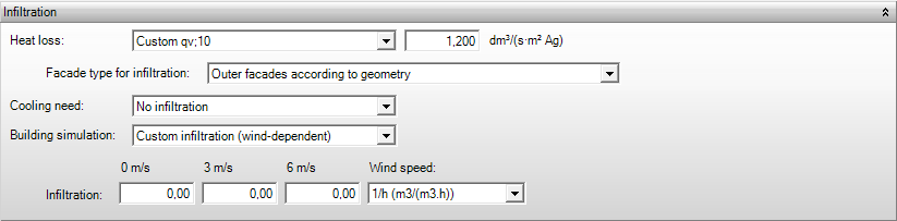
Heat loss
- Warmteverlies
Only for ISSO 2017: If a Building meets Dutch Building Code, the infiltration flow rate is determined for the calculations based on the specified qv;10 value (if applicable), the ventilation system (housing), and the Building dimensions: Level height of top floor (non-residential). Flow rates are given for buildings with and without openable windows for buildings which do not comply with the Dutch Building Code.
- Maximum qv; 10[dm³/(s.m²Ag)]In this case a maximum characteristic air permeability of the building envelope is assumed, used to determine the infiltration flow rate Qi. Please consult Infiltration flow rates for the applied values;
- Custom qv; 10[dm³/(s.m²Ag)]In this case the characteristic air permeability of the building envelope is specified, from which the infiltration flow rate Qi is determined;
- Custom infiltration[Select units *]In this case the infiltration flow rate is specified.
The qv10 can be calculated for older homes according to ISSO 51. For utility buildings (with rooms up to 4 meters), if it is not known, it is calculated according to ISSO 53 when a qv10 value of 0 is entered.
If the building does not comply, infiltration is determined using other tables, and more infiltration will be accounted for. Additionally, the minimum ventilation requirements of the Building Decree are not checked; the calculations are based on the specified ventilation flow rates.
Industry
For industry, according to ISSO 57, an infiltration rate is requested. If you specify your own qv10, Elements will prompt a message indicating that an infiltration rate of 0.2 will be used. This can be prevented by specifying your own infiltration rate, as Table 3.4 (ISSO 57, 2017) provides guideline values.
| Description | Infiltration rate ni [h-1]1) |
|
| Buildings before 1992 | 0,5 | |
| Buildings after 1992
or renovated after 1992 |
Box-shaped with volume ≥ 10,000 m³,
without skylights and/or fire dampers |
0,1 |
| Box-shaped with volume < 10,000 m³,
without skylights and/or fire dampers |
0,2 | |
| Box-shaped with volume ≥ 10,000 m³,
with skylights and/or fire dampers |
0,2 | |
| Box-shaped with volume < 10,000 m³,
with skylights and/or fire dampers |
0,3 | |
| Buildings of other shapes | 0,4 | |
| 1) n situations where (closed) doors are located opposite each other, increase the infiltration rate by 0.2 or apply Appendix C for more accurate calculation. | ||
| Note: For longer opened doors without additional measures to limit outdoor air entry, higher infiltration rates should be used. | ||
Facade type for infiltration
When calculating according to ISSO 51 (2023), you can specify how the fraction z is determined. Normally, the fraction z is determined based on the exterior walls according to geometry. In some cases, it may be useful to specify how the exterior walls of the space are located. If the current template is used by multiple spaces, make a copy of your current template. In this template, adjust the Exterior walls for determining the fraction z for the situation in that space.
- Exterior walls according to geometry: Typically, the fraction z of the space is determined based on the geometry.
- One exterior wall or two non-opposite exterior walls
- Two opposite exterior walls
- Other cases
Converting qv50 to qv10
Because Elements uses a qv10 value to calculate infiltrations, in some cases the qv50 value needs to be converted to a qv10 value. The conversion factor can be easily determined based on the airflow exponent (n), as shown in the overview below. For example, assuming an n-value of 0.5 (lower value leak), the qv10 value can be obtained by multiplying qv50 by 0.45 (qv10 = qv50 * conversion factor). For upper value airtight, an n-value of 0.75 can be used, and an average n-value of 0.66 can be assumed.
| n | Converting qv50 to qv10 | Source |
| 0,5 | 0,45 | Lower leakage limit according to Belgian research and SBR |
| 0,62 | 0,37 | Belgian research |
| 0,66 | 0,35 | TNO average |
| 0,75 | 0,3 | Upper limit airtight according to Belgian research |
| 1 | 0,2 | Upper limit airtight according to SBR guidelines |
Publications
ISSO Publicatie 53, paragraaf 4.7.1
ISSO Publicatie 57, paragraaf 3.7.1
Infiltration heat loss Φi
Cooling need
- Koellast
In general the infiltration is not taken into account in the cooling load calculations. It is also possible to use an infiltration rate of 0.30 in the calculations.
- No infiltration: no infiltration occurs;
- Custom infiltration [Select units *]: in this case the infiltration flow rate Qi is specified
Building simulation
- Gebouwsimulatie
The Building dimensions: Building height, which is to determine the infiltration flow rate, can be specified from Properties> Buildings> General.
Custom infiltration (wind-dependent)[Number]: a wind dependent infiltration flow rate Qi is defined. These infiltration flow rate may be specified at wind speed of 0, 3, and 6 m/s.
Explanation of infiltration for building simulation
For building simulation, determining the amount of infiltration can be challenging because there are few prescribed standards for this.
ISSO 32 specifies that a value of 0.20 air changes (for residential buildings) and 0.25 air changes (for utility buildings) can be used for all wind speeds.
For heat loss calculations, tables are provided in ISSO publications 51/53/57 for infiltration, assuming a wind speed of 5 m/s. These tables can be used, but it may be worth converting them for different wind speeds, especially for comfort calculations.
Note that rooms with two opposite walls have lower infiltration rates.
In the Vabi Elements library, you can find the following standard values for infiltration (1/h (m3/(m3·h))) :
| 0 m/s | 3 m/s | 6 m/s |
| 0,1 | 0,2 | 0,3 |
For new construction, more favorable values are often chosen:
| 0 m/s | 3 m/s | 6 m/s |
| 0,1 | 0,15 | 0,20 |
EPG
- EPG
The infiltration is partly determined based on the qv;10 value for the energy performance calculation EPG. The qv;10 value may be derived from the building properties (template Building requirements), or it may be user-specified based on measurements.
- Derived from building properties The qv;10 value is determined based on the implementation variant and building type (see template Building requirements).
- User-defined qv, 10 A user-defined qv;10 value in dm³/(s.m²Ag) is specified here. This value should have been determined based on measurements.
Publications
Infiltration
Calculation value for specific air permeability and correction for building type
Ventilation
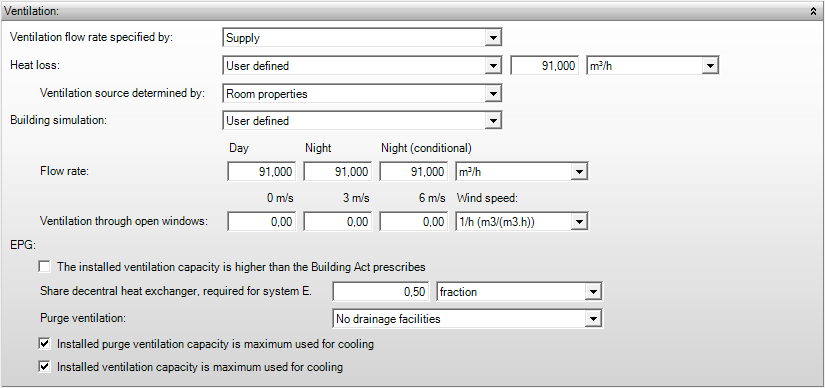
When you want to use the ventilation flows, it’s important to select the following inputs:
– Ventilation heat loss: User defined
– Ventilation source determined by: Room properties.
Ventilation flow rate specified by
- Gebouwsimulatie
- Warmteverlies
In this field it is determined whether the flow rate is specified by supply or exhaust. For example, habitable rooms need to be provided with fresh air, whereas the air should be extracted in toilet compartments and bathrooms.
- Supply, the ventilation flow rate is specified as supply
- Exhaust, the ventilation flow rate is specified as exhaust
Heat loss
- Warmteverlies
- According to building decree: the ventilation flow rate is determined automatically based on the utility function and room type as specified below Use > Room usage. The corresponding ventilation flow rate is taken from the table Ventilation flow in the Dutch Building Code.
- More ambitious than building decree[Factor]: the ventilation flow rate is determined automatically from Use > Room usage. The corresponding ventilation flow rate is taken from the table Ventilation flow in the Dutch Building Code. This flow rate is then multiplied by the specified multiplication factor.
- User defined [Select units *]: the ventilation flow rate is specified manually.
Publications
Ventilation source determined by
- Warmteverlies
The program tries its best to determine where the air is coming from. You can choose what the program should focus on:
- Room type and ventilation system: Based on the Room Type defined in the Use template and the selected Ventilation Facilities specified in the Delivery System template, the program determines where the air comes from. For rooms that are extracted, such as kitchens, toilets, and bathrooms, the air is drawn from adjacent rooms; usually from an adjacent circulation space or, in the case of (open) kitchens, from the adjacent living room.
- Ventilation system: The ventilation source is chosen based on the selected Ventilation Facilities under the Delivery System template.
- Room properties: The ventilation balance can be specified under Air exchange via building parts and Ventilation balance under room properties. This choice should be maintained when using the Ventilation test.
Ventilation system choice:
In case of ventilation systems with natural supply of ventilation air, the outside air is used in the calculations for habitable rooms and spaces.
- In mechanical supply, the air of the system is used in the calculations;
- In natural supply the outside air is used in the calculations (irrespective of the presence or absence of mechanical exhaust), unless an interior room is considered. In the latter case, the air is extracted from an adjacent room.
- In other rooms, the air from adjacent rooms is used in the calculations by default.
Note that the software will not execute these choices well in all cases; therefore, a thorough verification on its performance is recommended. Additionally, the software will not make a ventilation balance of the surcharged air. The choice of room type and ventilation system is used to perform a ventilation calculation quickly and automatically using the minimum ventilation requirements and the user-defined flow rates. When choosing ‘room properties’, a balance can be made by indicating the amount of air which enters and/or leaves the room.
In Properties> Rooms> Ventilation Balance it can be indicated how much air enters from other rooms or from outside. The total amount of air is in balance at all times, i.e. the amount of air which enters the room is the same as the amount of air leaving the room. A correct balance can be made by specifying the right flow rates of ventilation air and the origin of the air.
Building simulation
- Gebouwsimulatie
The ventilation properties for the building simulation are specified for day, night, and night (conditional). These correspond to the daytime operation and night time operation as defined in Schedule of HVAC.
- Custom value[select units *]: a ventilation flow rate is specified.
Publications
Ventilation
Ventilation through open windows
- Gebouwsimulatie
This is the ventilation flow rate in case the windows are fully open, which is defined for various wind speeds. This flow rate is only included when the windows are open; it is not included if Building operation >Openable windows > Windows stay closed has been activated.
What do I enter here?
The ventilation flow rate through open windows can be difficult to estimate, especially because it depends on factors like whether windows are open in opposite directions and the wind direction hitting that facade. As a rule of thumb, you can take a multiple of 1 m/s times the window area and increase this flow rate as the wind speed increases. In high-rise buildings, the pressure difference on the facade may also allow for a higher ventilation rate compared to the same facade openings in low-rise buildings.
When determining the purge ventilation according to NEN1087, this flow rate is determined at a wind speed of 2 m/s (see section 5.4.1 of NEN1087).
EPG
The installed ventilation power is higher than prescribed by the Dutch Building Code
- EPG
The actual ventilation power which is to be installed can be applied in the EPG calculation. By checking this box, the ventilation flow rate for the room can be specified. If this option has been chosen in one of the rooms within a zone, the specified ventilation power is summed for all rooms within the zone. Additionally the true ventilation power is used in the calculations for the ventilation system defined within the zone (and possibly in multiple zones). If this box is not checked in any of the rooms within a zone of the ventilation system, then the minimum ventilation requirements are used in the calculations.
Ventilation power installed in room
- EPG
The actual ventilation power in the room within a zone can be specified using multiple units. In the EPG calculation, the flow rates are computed in dm3/s and displayed in the results.
Share decentralized heat recovery, required for system E
- EPG
This field allows you to indicate what share of the air is preheated using the heat recovery. It applies to housing and it is used in the energy performance calculation EPG. The share can be specified as a fraction, or based on the utility surface of the rooms (living room). This fraction or utility surface does not hold per room, but rather for the complete zone in which the room is located.
Purge facility
- EPG
The purge facility which is used in the building or part of the building can be indicated here. By default, openable windows are assumed in housing, irrespective of the input for the purge facility. If a purge facility is defined it is applied in the complete system, potentially also in different zone.
Installed ventilation capacity is maximum used for cooling
- EPG
This indicates the installed ventilation capacity is used completely for cooling of the building. In this case the cooling load for the building can be reduced.
Installed purge ventilation capacity is maximum used for cooling
- EPG
This indicates the installed purge ventilation capacity is used completely for cooling of the building. In this case the cooling load for the building can be reduced.
Number of persons

Number of persons
- Gebouwsimulatie
- Warmteverlies
- Koellast
- EPG
Heat loss: the number of people is required for the ventilation requirements of the Dutch Building Code 2012, in order to compute the minimum ventilation requirements according to ISSO 53. Additionally, the number of people is important for the (minimum) ventilation in rooms which are higher than 4 m (according to ISSO 57).
Heat loss, cooling load, building simulation, and EPG: The number of people is required if the infiltration/ventilation has been specified with units depending on this number of people. The input in this field has no relation to the internal heat gain by people.
- People: the number of people in the room.
- People per m2: the number of people per m2 in the room.
- m2 per person: the number of m2 per person in the room.
Open combustion unit

Zone contains open combustion unit
- EPG
This box indicates if the zone contains an open combustion unit. Extra ventilation air is surcharged for such an open combustion unit. Examples of open combustions units are geysers, boilers, gas stoves, or fireplaces which extract air for combustion from the heated calculation zones. Only one combustion unit can be specified per zone.
Type of combustion
- EPG
The type of combustion unit within the heated calculation zone is indicated here. The specific air volume flow required for this combustion unit, and a correction factor for operation time are determined depending on the type of combustion unit.
Nominal load
- EPG
The nominal load of the combustion unit determines the air volume flow required for the combustion unit. The minimum values for nominal load are applied in case the power is not specified or the specified power is too low.
Publications
Share of combustion air for open combustion appliances
Recirculation rate

Reduction for circulation rate
- Warmteverlies
- ISSO 57
In rooms which are higher than 4 metres, the heating system mainly determines the temperature gradient in the room. The recirculation rate leads to a reduction in this temperature gradient. The corresponding reduction factor can be indicated here; it should be determined based on ISSO 57, Table 2.15 and Figure 2.6.
Publications
Reductiefactor r afhankelijk van het circulatievoud