Building parts
The building parts screen shows a list of all building parts. You can see that all constructions are now automatically assigned. The geometry help screen is also available here. In the building components screen, you can see for each building component the back side, construction, surface orientation, and slope of the building component. You can also enter a reveal (space between the front of the facade (brickwork) and the front of the window frame), if applicable (for solar radiation building simulation and cooling load).
Under Tools – Constructions, you can assign colors to the constructions. You can now see these clearly in the geometry help screen.
Reverse or modify construction
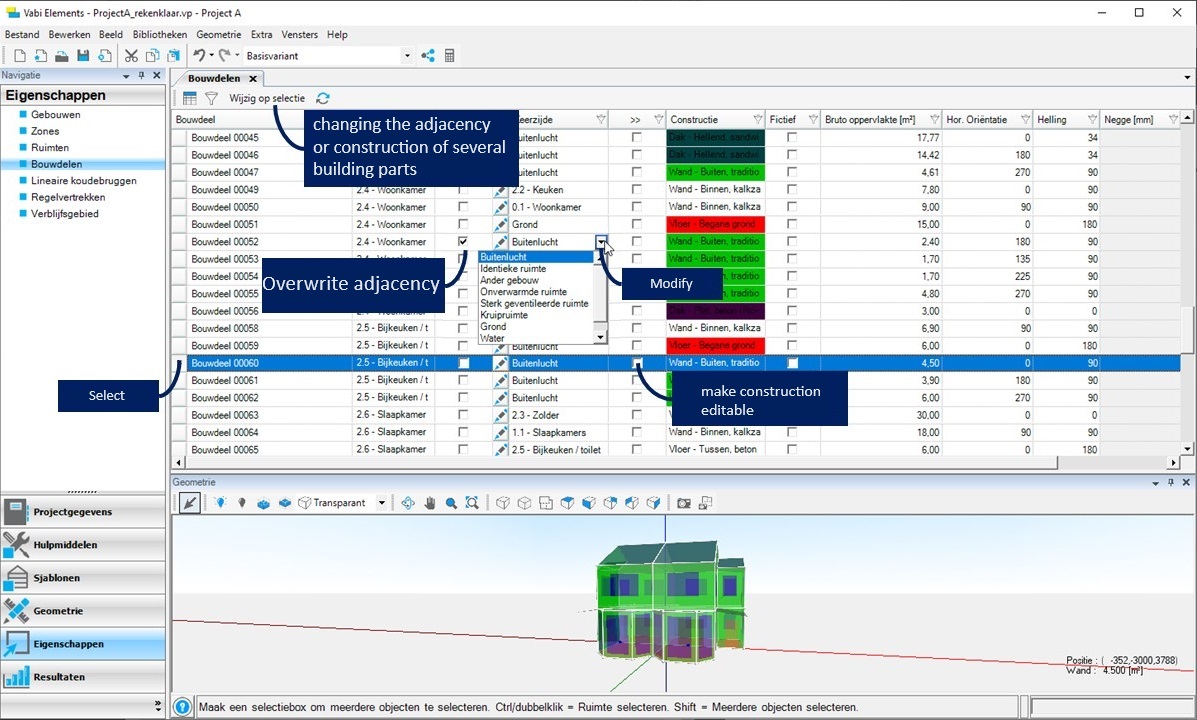
When a part of your building adjoins another building or crawl space, you can draw these in the geometry. You can also modify the back side of the building components that would border that building or crawl space.
Check the box to override the back side or construction in the column >>. Once it’s been changed, a checkmark will remain. If you want to reset the construction or back side according to the geometry again, you can uncheck the override option.
For example, for a single-family home (or a single apartment), you can only draw the calculated dwelling and specify the side walls (possibly the upper and lower floors) towards the neighbors as “other building” for the back side. In this case, you do not use zones within the building. However, if you want to analyze different apartments within an apartment complex, each individual apartment is considered a zone, and you must draw the surrounding buildings as well and assign a separate zone to each.
Additional
Number of adjacent buildings refers to the number of buildings that are attached to the building being analyzed.
When selecting “Other building” for the back side, you can choose between “1” or “2 or more” adjacent buildings. If both “1” and “2 or more” are assigned as the back side, the one resulting in the lowest adjacent temperature (i.e., 1 adjacent building) will be applied to the entire building.
For heat loss, the adjacent temperature is determined according to ISSO 51 paragraph 4.5.
Adjusting multiple building components simultaneously
With SHIFT pressed, select the floor constructions, for example, those that should adjoin a crawl space. (Tip: sort by back side, and you can select all components that adjoin the ground at once). Click on Edit Selection and choose the desired back side with its associated properties.
Other adjustments
Fictitious
- Warmteverlies
The column “Fictitious” provides the option to mark a building component as fictitious. Making a building component fictitious applies only to components that are located between two spaces. This option is applicable only for heat loss calculations. When a building component is marked as fictitious, the spaces on either side of the component are treated as a single space, and no transmission through the respective construction is calculated.
Negge
The “Reveal” column provides the option to indicate whether a window is set back or if there is a reveal. In the project settings, you can specify whether the reveal is taken into account in the shadow calculation.
When a window is set deep within the facade (a deep reveal), this can be indicated here. The depth is entered in millimeters. The depth is used to determine solar irradiation. If there is a reveal, there is also shading caused by this reveal. This shading is taken into account in all solar incidence angles.
Filters
In the table of Building Parts, each column has a filter button visible. When a filter is active, this button lights up. The filter buttons allow choices to be made per column to show which building components are visible in the table. This makes it easy to create various overviews of types of building components. In each column, you can choose a filter from the list or define a filter yourself.
Additional information for determining the transmission losses of ground floors according to EPG and NEN 1068:2012.
Extra information for determining the transmission losses through the ground floor:
Ground floors are categorized based on the boundary of the floor:
- Ground floors at or above ground level, directly on the ground (potentially with an air layer of maximum 30 cm).
- Ground floors above a crawl space.
- Ground floors above an unheated basement.
- Ground floors of a heated space with the floor below ground level.
For each boundary of the ground floor, the loss through the floor is calculated separately. The loss through the floors is determined by the applied constructions, the boundaries of those constructions (open air or ground), and the linear thermal bridges of the floors (either estimated via the perimeter or detailed through the linear thermal bridges).
It is important within the calculation zone to define only one type of boundary for the ground floor. If different types of ground floor boundaries exist within the calculation zones, the zones should be split into multiple calculation zones. It is also important to correctly distribute the linear thermal bridges (perimeter) across the calculation zones.
Ground
The floor directly on the ground at or above ground level can be specified via ‘Properties’ and ‘Building Components’ by choosing ‘Ground’ for the back side. For EPG calculations, no additional input for the ground boundary is required. If the floor is located above an air layer, the air layer should be included in the thermal resistance of the construction.
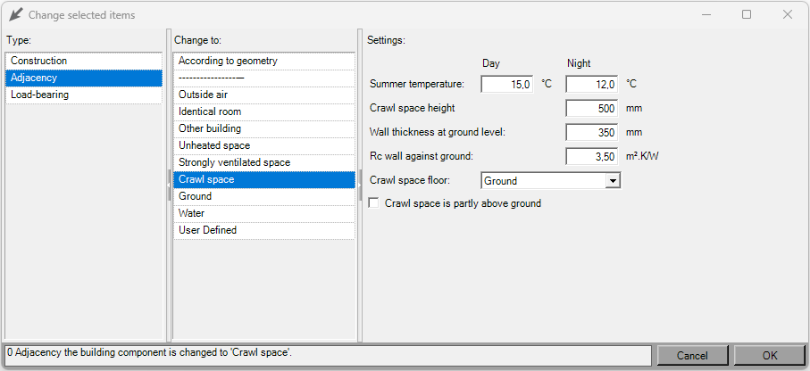
Crawl Space
The floor above a crawl space can be specified via ‘Properties’ and ‘Building Components’ by choosing ‘Crawl space’ for the back side. For EPG calculations, several input data of the crawl space are required:
- Height of the adjacent crawl space in mm
- Thickness in mm and R-value in m²·K/W of the ground-facing wall of the crawl space
- Floor of the crawl space (ground, insulation on the ground, or separate construction)
- Ground: no additional input needed
- Insulation: thermal resistance of the insulation of the crawl space floor (insulation on the floor of the crawl space)Construction: thermal resistance of the construction of the crawl space floor
- Is the crawl space partially above ground level?
-
- Height above ground level in mm
- Thermal resistance of the construction in m²·K/W of the crawl space wall adjacent to the outside air
If different input data for the crawl space are provided for the adjacent crawl spaces within the calculation zone, the data is surface-weighted averaged for the adjacent crawl space.
Unheated Basement
For the ground floor above an unheated basement, first, a separate zone must be created. For the space or spaces of the unheated basement, a heat transfer template must be created where no heat transfer devices are specified for heating (unheated space). For the unheated space or spaces, the walls and floors must be specified as building components adjoining the ground.
If the unheated basement is partially above ground, the walls must be divided into parts adjoining the ground and parts adjoining the outside air. The ground level height can be specified using the ‘Ground Level Height’ icon in the geometry drawing screen. By drawing additional lines within a space on a wall, walls can be divided into multiple sub-walls for which different boundaries
Below ground level
Ground floors of a heated space with the floor below ground level can be specified by adjusting the height using the ‘Ground Level Height’ icon in the geometry drawing screen and specifying walls and floors against the ground where necessary.